

Nordskog GPS speedometer wiring..

 06-19-2016, 06:10 PM
#3
Found it,,,
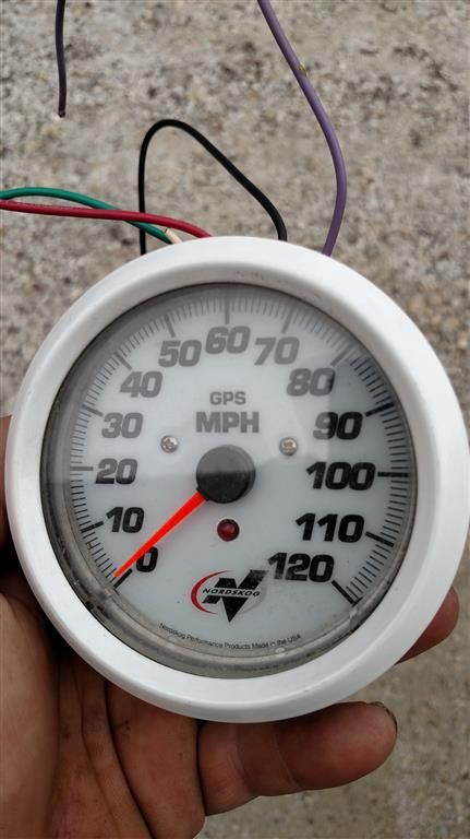
Black......Ground
Red........To a switched +12 volt source
Purple.....Lighting the gauge face, hook to running lights
Connect the green wire to to one terminal of supplied toggle switch, connect the other terminal to ground, this is to change modes.
Gray........is used for the intergrated tach, connect to the -neg. side of coil
White......is for hook up to GPS signal source other than that supplied by Nordskog
ndat=no data, speedo not commuting with gps receiver
Last edited by Boatally Insane; 06-19-2016 at 06:39 PM.


