

wiring safety switch for electric fuel pump
 03-18-2019, 06:34 PM
#1
I have purchased a holley oil pressure safety switch for the purpose of trying not to die in a gasoline fire on my boat.
I have found a number of wiring diagrams for wiring this thing. I would like to do it the way in the attached diagram, but just want to make sure it is safe in a marine application.
In the attached diagram it shows a wire going from the ignition switch to the NO terminal on the switch. Is this the wire that is only hot when I am turning the engine over, or the wire that is hot when the key is turned to the 'on' position? Looks to me like it is the wire that is only hot when the starter is cranking the engine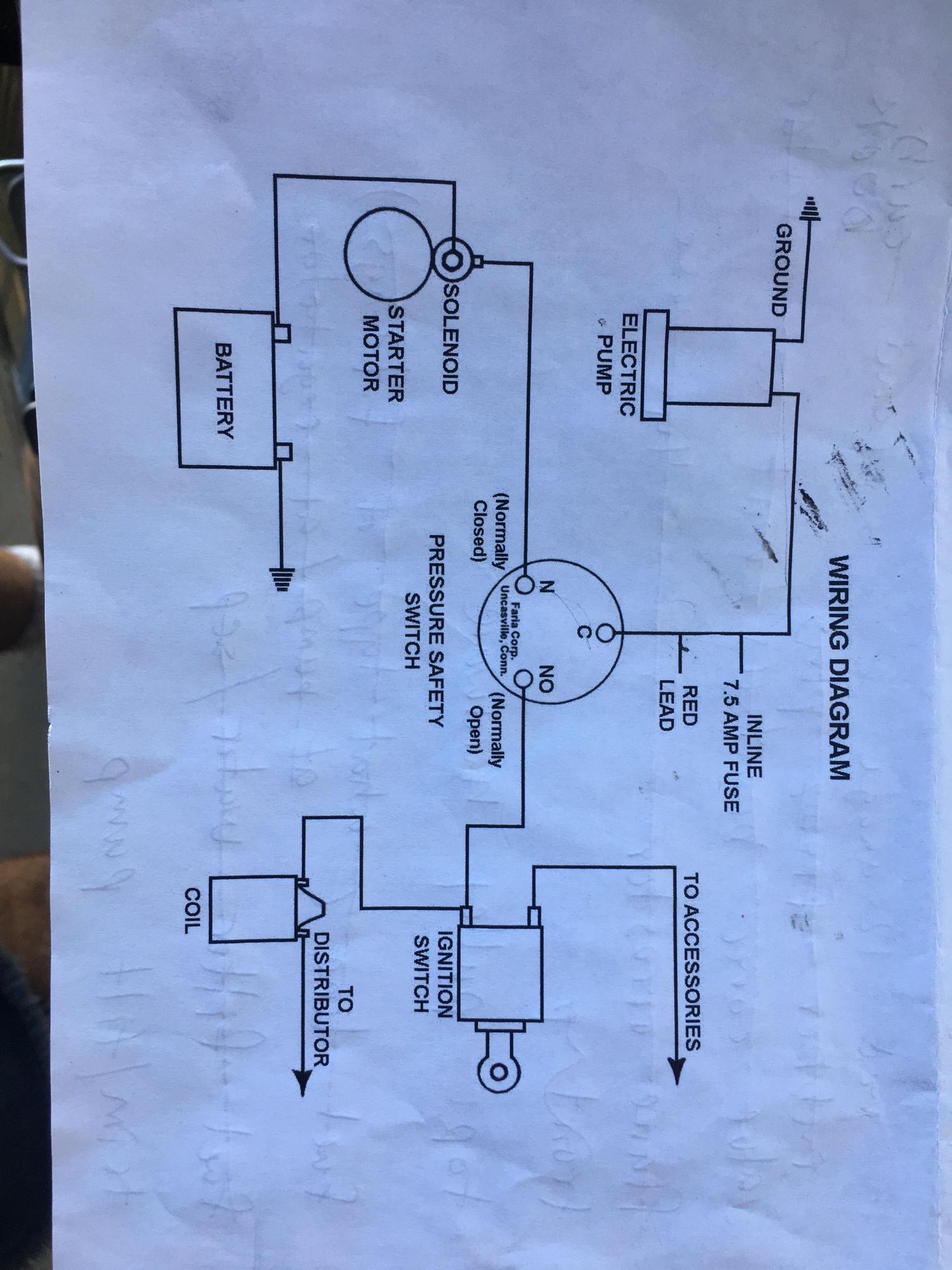 .
.
Thanks for the help......this wiring stuff gives me a real pain in the ass. I am reinstalling a new motor after having it out all winter and the wiring harness looks completely foreign to me now. lol.
Thanks for the help,
Russ
I have found a number of wiring diagrams for wiring this thing. I would like to do it the way in the attached diagram, but just want to make sure it is safe in a marine application.
In the attached diagram it shows a wire going from the ignition switch to the NO terminal on the switch. Is this the wire that is only hot when I am turning the engine over, or the wire that is hot when the key is turned to the 'on' position? Looks to me like it is the wire that is only hot when the starter is cranking the engine
.Thanks for the help......this wiring stuff gives me a real pain in the ass. I am reinstalling a new motor after having it out all winter and the wiring harness looks completely foreign to me now. lol.
Thanks for the help,
Russ
 03-18-2019, 07:35 PM
#2
Registered
Join Date: Sep 2007
Posts: 20
Likes: 0
Received 0 Likes
on
0 Posts
Russ,
I would look for a better/complete diagram. It shows the starter solenoid wire and the distributor coil wire connected to same pin on the switch (which is not/will not work). I think that diagram is more for illustrative purposes than an actual diagram to wire from.
I would look for a better/complete diagram. It shows the starter solenoid wire and the distributor coil wire connected to same pin on the switch (which is not/will not work). I think that diagram is more for illustrative purposes than an actual diagram to wire from.
03-20-2019, 08:23 AM
#3
Russ,
I would look for a better/complete diagram. It shows the starter solenoid wire and the distributor coil wire connected to same pin on the switch (which is not/will not work). I think that diagram is more for illustrative purposes than an actual diagram to wire from.
I would look for a better/complete diagram. It shows the starter solenoid wire and the distributor coil wire connected to same pin on the switch (which is not/will not work). I think that diagram is more for illustrative purposes than an actual diagram to wire from.
03-20-2019, 09:49 AM
#4
That diagram will work if that pressure switch works the way its intended to.....
So the way they are illustrating that is when the starter is cranking it is sending a signal from the solenoid to activate the fuel pump.....so the NC (normally closed ) terminal will be connected to the C (common) terminal. When the engine starts and pressure is there, the pressure safety switch will close and the C terminal will be connected with the NO (normally open) and the pump will run off the ignition side of the start switch. So to answer your question....you should wire the key switch side with a signal that's hot when running
So the way they are illustrating that is when the starter is cranking it is sending a signal from the solenoid to activate the fuel pump.....so the NC (normally closed ) terminal will be connected to the C (common) terminal. When the engine starts and pressure is there, the pressure safety switch will close and the C terminal will be connected with the NO (normally open) and the pump will run off the ignition side of the start switch. So to answer your question....you should wire the key switch side with a signal that's hot when running
__________________
-Wally
Money can't buy happiness, but it can buy horsepower. And I've never seen a sad person hauling a$$!
-Wally
Money can't buy happiness, but it can buy horsepower. And I've never seen a sad person hauling a$$!
03-20-2019, 11:09 AM
#5
That diagram will work if that pressure switch works the way its intended to.....
So the way they are illustrating that is when the starter is cranking it is sending a signal from the solenoid to activate the fuel pump.....so the NC (normally closed ) terminal will be connected to the C (common) terminal. When the engine starts and pressure is there, the pressure safety switch will close and the C terminal will be connected with the NO (normally open) and the pump will run off the ignition side of the start switch. So to answer your question....you should wire the key switch side with a signal that's hot when running
So the way they are illustrating that is when the starter is cranking it is sending a signal from the solenoid to activate the fuel pump.....so the NC (normally closed ) terminal will be connected to the C (common) terminal. When the engine starts and pressure is there, the pressure safety switch will close and the C terminal will be connected with the NO (normally open) and the pump will run off the ignition side of the start switch. So to answer your question....you should wire the key switch side with a signal that's hot when running
03-20-2019, 12:06 PM
#6

__________________
-Wally
Money can't buy happiness, but it can buy horsepower. And I've never seen a sad person hauling a$$!
-Wally
Money can't buy happiness, but it can buy horsepower. And I've never seen a sad person hauling a$$!
03-20-2019, 12:20 PM
#7
If it were me i would also add a relay to actually run the fuel pump with some good proper voltage/current instead of running the power through who knows what size wires throughout the boat. So it would go between the safety switch and fuel pump and the wire from the safety switch would be the trigger for the relay to activate the pump...
__________________
-Wally
Money can't buy happiness, but it can buy horsepower. And I've never seen a sad person hauling a$$!
-Wally
Money can't buy happiness, but it can buy horsepower. And I've never seen a sad person hauling a$$!
03-20-2019, 04:56 PM
#8
Registered
I couldn't tell you what wires are hooked to what terminal but that was the switch I had in my old Donzi. One wire to the key, one to the to the starter and one to the pump. I thought one wire went to the ignition (S) switch terminal (the one that spins the starter) so the pump will run while you are cranking the starter. Then the Poss wire from the starter to the switch took over once the motor make 5lbs of oil pressure. I haven't owned the boat in a couple years so....
03-23-2019, 08:18 AM
#9
Registered
That diagram is how I wire my safety switches , Except on the common ( C ) side of the switch , I install a relay .
Just let the wire actuate the relay , so they Ign System doesnt carry the load of the Fuel Pump Motor.
Just let the wire actuate the relay , so they Ign System doesnt carry the load of the Fuel Pump Motor.
03-23-2019, 10:59 AM
#10
ok, thanks for all the comments. That diagram is the one that came from Holley. I am going along as a couple of you said as per the diagram but adding in a relay between the C terminal of the switch and the pump itself.
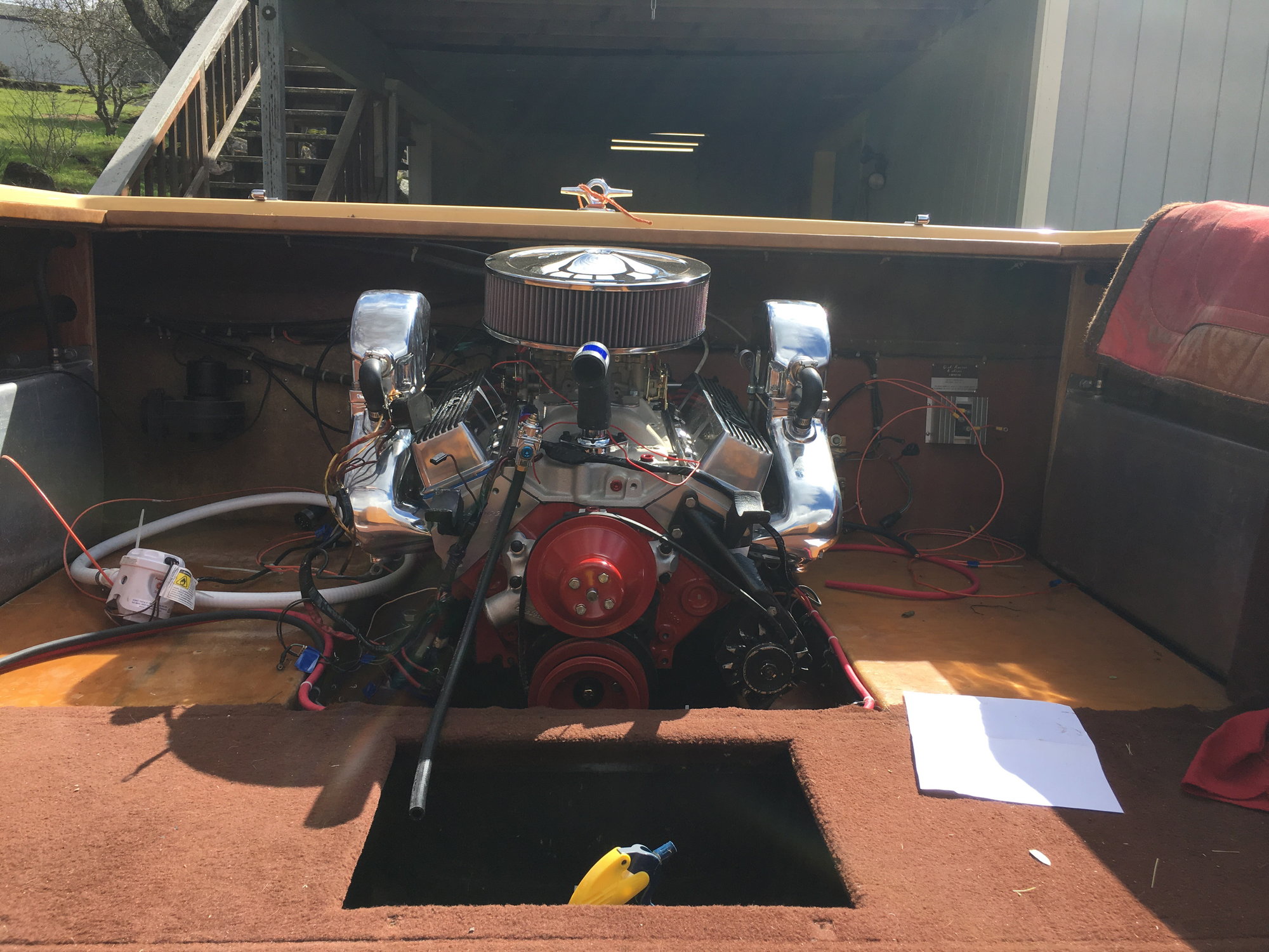
My boat is old and I have made a lot changes and now am going to have a few relays in the engine compartment. Trying to figure out a decent way to organize them.
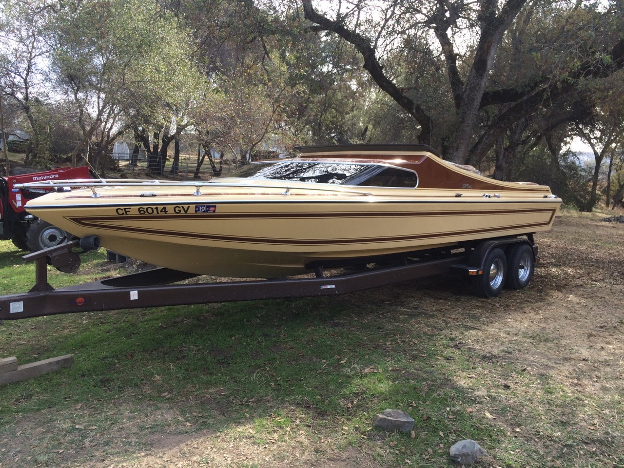
I attached a couple pictures of my old boat.
thanks again.

Russ
My boat is old and I have made a lot changes and now am going to have a few relays in the engine compartment. Trying to figure out a decent way to organize them.
I attached a couple pictures of my old boat.
thanks again.
Russ

