

Adding trim switches to throttle or helm

 02-17-2023, 09:58 PM
#42
Registered
02-23-2023, 06:13 PM
#43
Registered
iTrader: (1)
I added throttle trim tab and drive repeater switches on my Fountain about six years ago. From what I remember after tracking wires from dash switches to trim pumps you will need to wire up relays and diodes. If you install that switch bundle with the 20-22 gauge wire you will burn it up. It will not take the amps that go through the circuit to the pump motors without a relay. A relay is a high amp capacity switch. It uses low amperage to close the contact on the relay. The contact is what is rated for high amps. I mounted my relays under my dash and pulled power off the original switches through them. The relays and diodes are common items. For what it’s worth, Drive Sync is worth the money. Wouldn’t ever go back to a boat without it.
Last edited by mike38scarab; 02-23-2023 at 06:50 PM.
05-25-2023, 02:44 PM
#44
Platinum Member
Thread Starter
iTrader: (2)
So I got it done.
All of the parts that I ended up receiving were a little too large for the Merc Zero Effort controls on my Formula so I had to improvise.

The diameter was reduced by about 3 mm. Screws relocated to fit inside the Merc handle (the handle needed to be hogged out fit the screws even after being relocated). Backing plate drilled and tapped.
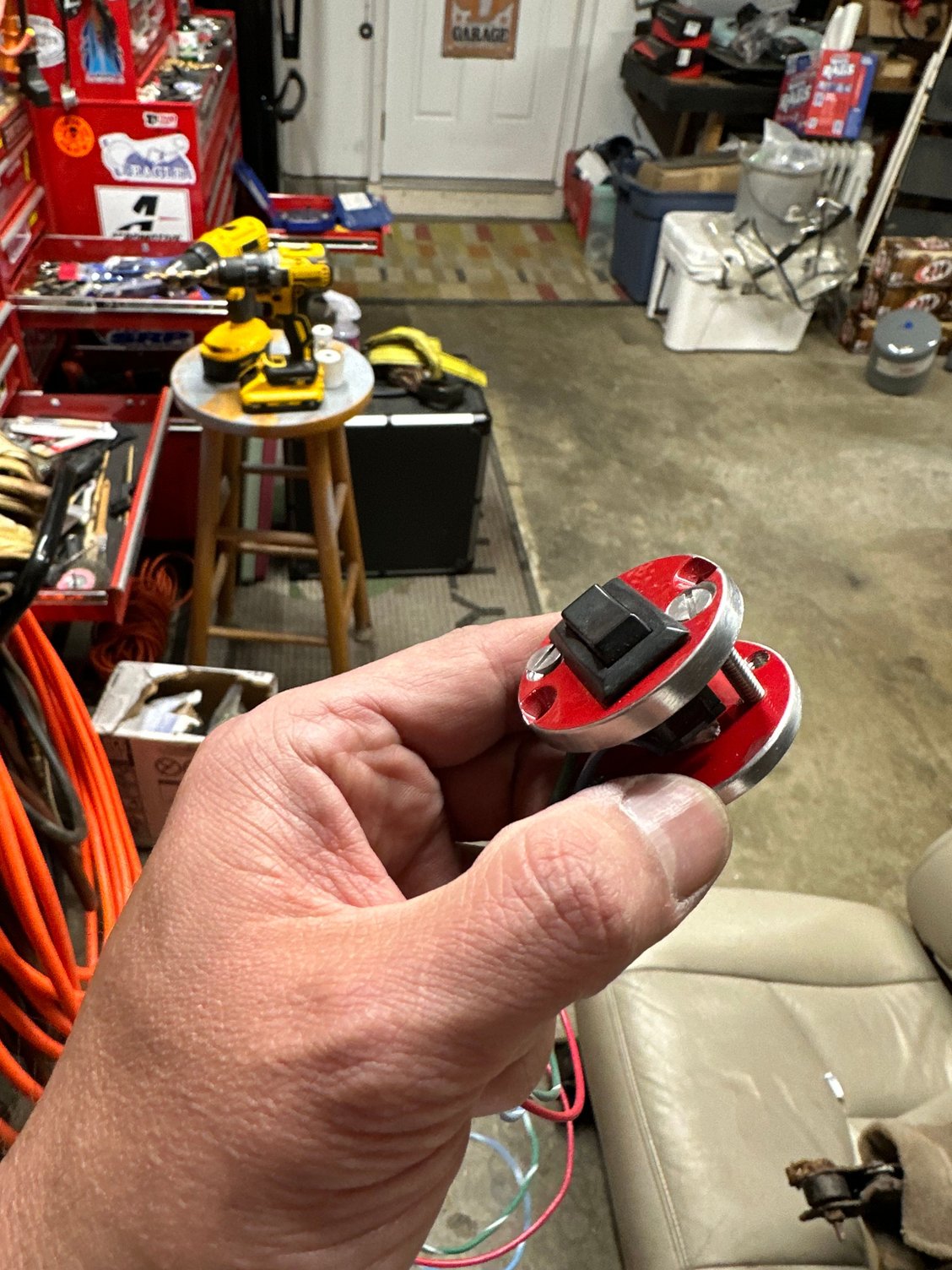
Test assembled and fit into the handle (handle and subsequent clearance of the handle bore not shown… it was a lot).
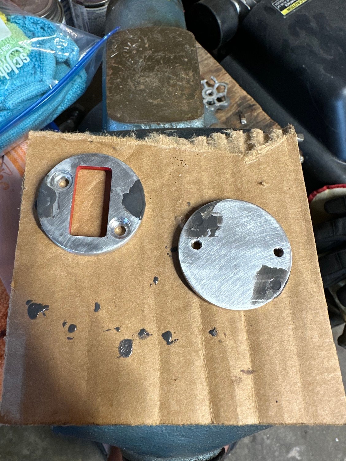
JB Weld mixed up to cover the old screw holes.

Sanded and ready to paint. What’s not shown in the channel cut into the backing plate for the wires to lay into a recess on the backside of the handle. This guarantees that nothing will be pinched. Wiring was also covered with a heat shrink tube.

Ready to go in the handle. Is used weather pack connectors to make a macular harness. The other side of the harness contains the diodes.

Installed and working. The angle is perfect for running. One of my buddies said I should have mounted it horizontally, but I tested it a few ways, and this one was best. The JB Weld left some dimples from air pockets… I let them be.
All in all it turned out great - very functional!
All of the parts that I ended up receiving were a little too large for the Merc Zero Effort controls on my Formula so I had to improvise.
The diameter was reduced by about 3 mm. Screws relocated to fit inside the Merc handle (the handle needed to be hogged out fit the screws even after being relocated). Backing plate drilled and tapped.
Test assembled and fit into the handle (handle and subsequent clearance of the handle bore not shown… it was a lot).
JB Weld mixed up to cover the old screw holes.
Sanded and ready to paint. What’s not shown in the channel cut into the backing plate for the wires to lay into a recess on the backside of the handle. This guarantees that nothing will be pinched. Wiring was also covered with a heat shrink tube.
Ready to go in the handle. Is used weather pack connectors to make a macular harness. The other side of the harness contains the diodes.
Installed and working. The angle is perfect for running. One of my buddies said I should have mounted it horizontally, but I tested it a few ways, and this one was best. The JB Weld left some dimples from air pockets… I let them be.
All in all it turned out great - very functional!
The following users liked this post:
Wally (05-25-2023)
05-26-2023, 07:58 AM
#47
Registered
05-26-2023, 09:11 AM
#48
Platinum Member
Thread Starter
iTrader: (2)
I do. They’re all tied in together with diodes to prevent power flow back through the single switch (without the diodes all three switches would control the drives at the same time).
05-26-2023, 09:26 AM
#49
Registered
Roger! I learned about "one-way" diodes in my single electrical engineering class...which I had to take twice :-(


