

DIY - Duramax Marinisation
 08-23-2017, 02:32 AM
#181
Registered
Thread Starter
Now that we've covered the important modules on the harness, we can move onto the power, grounds, and required relays to make everything run happily in a boat. I was going to use the example harness with fuse block above, then found out why it's easier to scrap the OEM fuse block. They are prone to connector corrosion issues, and that one had developed some since pulled from last build. So it's cut out now...
Rather than explain pinout wire by wire with poor quality photos, I found a great 4 part engine swap YouTube video that someone put together several years ago. This series explains it all exactly as I was planning, but faster and with options to pause and rewind. So I'll pick up where he is cutting the unused wires from his harness.
Thanks Carl..
 08-25-2017, 11:47 PM
#182
Registered
Thread Starter
Hope everyone enjoyed Carl's video breakdown on the LMM stand alone harness mod. Actually he only recorded 3 parts, but that much covered everything ya need to start cutting tape and wires. Mostly tape, and chop a few wires to separate everything unneeded from our ECM donor harness. So here is the short and sweet.
First we ditch the factory fuse block, then remove the TCM plug and transmission harness. What should be left is a very short chassis harness that only requires a few new connections to make an engine run again. In the pictures below I started by isolating the point where ECM harness meets the TCM harness. Carefully cut and remove the tape in this area to expose all the TCM harness wires. Pull the TCM connector and transmission harness to one side and isolate the dozen or so wires from it going to the main ECM harness.
You should see 1 red/white, 1 pink, a twisted pair with tan & tan/black, and maybe 3 or 4 other wires linking the transmission harness to the ECM harness. Cut them all,, on the TCM side, using slightly different lengths so ya can tape up the engine harness without fear of any ends touching. Don't worry, your only going to use 2 of those ever again. Just the twisted pair tan tan/back high speed data wires, that's it.
08-26-2017, 12:10 AM
#183
Registered
Thread Starter
Now besides a floor covered with black tape, you should have a separate transmission harness, and a fairly short chassis harness with 2 ECM connectors, 2 engine harness connectors, our X109 to APP, lead with alternator and MAF plugs, and our X2 power block connector with all the pink wires. You can now un-tape the wires from the X2 connector as we are going to chop that puppy off next.
No I didn't label all the wires on the X2 as Carl suggested.. I prefer to verify each by continuity at the ECM and GPR connectors once everything is cleaned up and ready to join our new fuse / relay block. But first timers should probably follow Carl's advice....
No I didn't label all the wires on the X2 as Carl suggested.. I prefer to verify each by continuity at the ECM and GPR connectors once everything is cleaned up and ready to join our new fuse / relay block. But first timers should probably follow Carl's advice....
08-26-2017, 01:14 AM
#184
Registered
Thread Starter
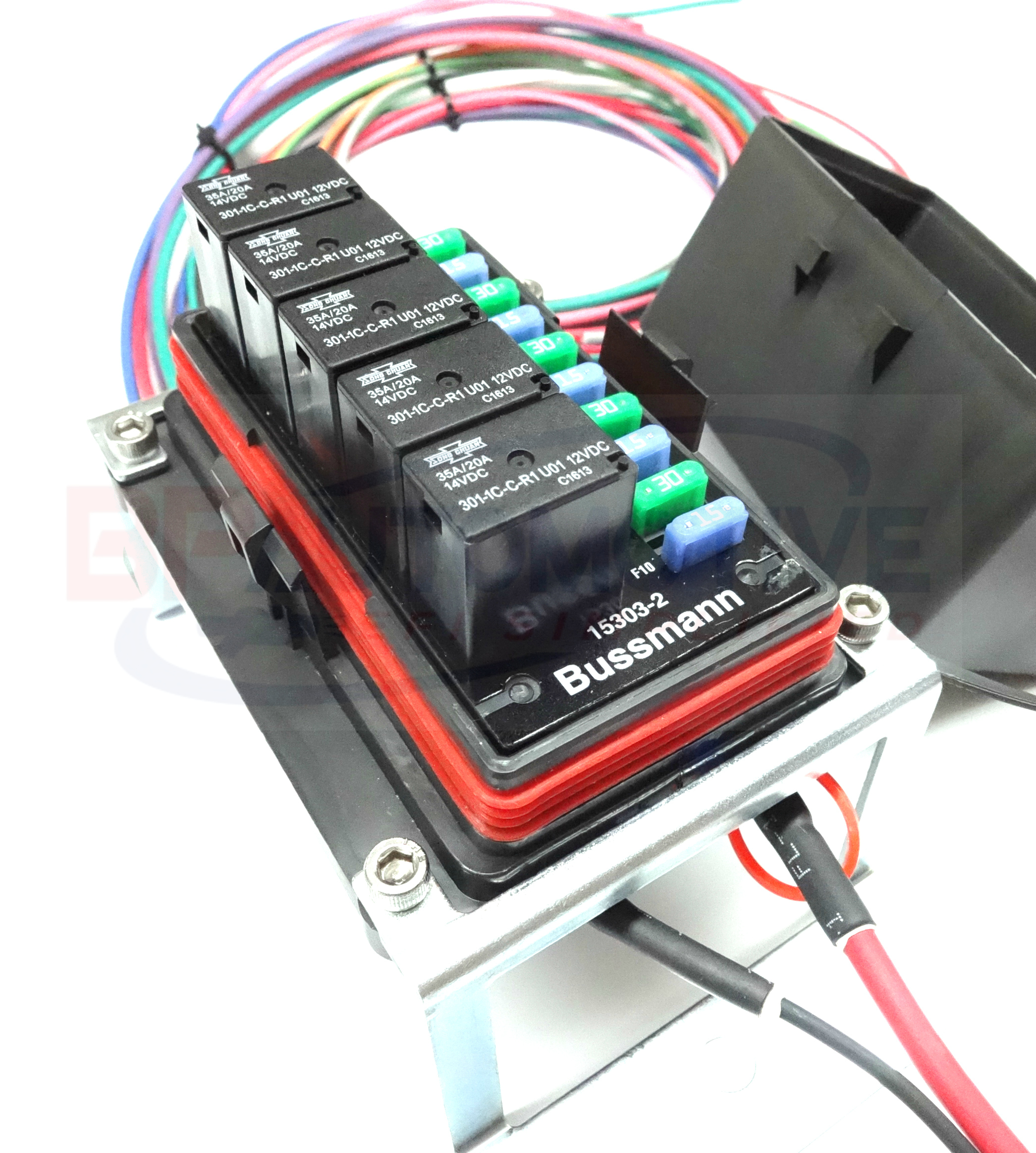
Next we need to choose a new fuse / relay block to replacement for the OEM truck unit we just eleminated. While you could get by with a few inline fuse holders and wiring everything to the key switch, I like to use these clean little series_15300_rtmr.html.
Compact, water resistant, with backside wiring makes for a very clean looking install. I prefer the 5x35amp relay, 10 mini fuse combo. You can order these in several configurations for under $50 off Amazon or electronic hardware sites. However that doesn't include terminals, seals, wires, fuses, relays or a good crimp tool..

However,, you could just order a pre-wired, with all relays and fuses included, for about $120 off Ebay or Amazon. Likely saving you 2 or 3 hours, or more custom wring it. Your probably gonna need to add some length to the power and ignition wires on the chassis harness anyways. So do a search for Waterproof Universal Off Road Relay and Fuse Power Distribution and you'll find several options with 3' drop leads off each fuse and relay. Just make certain it has the rear mounted power studs option so you can install your own main power and ground leads with no splices.
Let's pick up at wiring one of these into our harness next week. I'm done.
Compact, water resistant, with backside wiring makes for a very clean looking install. I prefer the 5x35amp relay, 10 mini fuse combo. You can order these in several configurations for under $50 off Amazon or electronic hardware sites. However that doesn't include terminals, seals, wires, fuses, relays or a good crimp tool..

However,, you could just order a pre-wired, with all relays and fuses included, for about $120 off Ebay or Amazon. Likely saving you 2 or 3 hours, or more custom wring it. Your probably gonna need to add some length to the power and ignition wires on the chassis harness anyways. So do a search for Waterproof Universal Off Road Relay and Fuse Power Distribution and you'll find several options with 3' drop leads off each fuse and relay. Just make certain it has the rear mounted power studs option so you can install your own main power and ground leads with no splices.

Let's pick up at wiring one of these into our harness next week. I'm done.
Last edited by kidturbo; 08-26-2017 at 01:18 AM.
09-19-2017, 12:39 AM
#185
Registered
Thread Starter
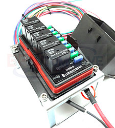
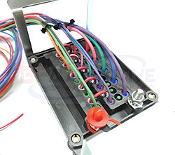
Attached is the Bussmann fuse / relay block I purchased off eBay for a build. Came pre-wired along with 35amp relays, fuses, barrel crimp connectors, and glue type heat shrink tubes. Everything ya need for a clean and easy install.
One thing to note, these pre-wired units come with all the relay ground terminals tied to single buss bar. Each relay is triggered by applying positive voltage over a low amperage signal wire. While the relays in our factory OEM fuse block were triggered by a grounding signal from the ECM.
In a truck, when you turn the key to run and start, the Body Control Module [BCM] receives a signal from the key security module over low speed data network. The BCM then sends a command over the high speed GMLAN network telling the ECM to ground the Power Train Relay [PTR] and start relay. Since we don't use a BCM in such stand alone setups, we can't tell the ECM to trigger the PTR or start relay. So we'll do this the old fashion way, with a positive voltage from our key to activate both relays. However, we you have to disable VATS in the ECM using EFIlive or other custom tuner software, or it will crank but not fire injectors. Little GM safety to make sure you can hotwire a truck under the hood and drive off... More on that later.
Last edited by kidturbo; 09-19-2017 at 12:42 AM.
09-19-2017, 01:14 AM
#186
Registered
Thread Starter
Now lets find all the Battery +, Ignition, and grounds our ECM and engine harness needs to make our engine crank and run. Then we'll transfer these circuits to our new Bussmann relay box.
First lets dig up a good diagram showing factory power flow schematics. While the documument I listed above are ok, I found that Autozone actually has the real GM schematics under their help pages. Just type in the year of your donor vehicle and you'll find everything you need.
In the attached photo you'll find all the power circuit numbers, fuse amperage ratings, and ECM pins for each. For this example we are using the LBZ/LMM model year. So there is two ECM connectors, X1 & X2.
At top we start with battery voltage in RED. Followed by every circuit connected to our factory PTR power train relay. All the circuit ID's I have outlined in ORANGE. And at the bottom, is our ECM pins which I have outlined in colors corisponding to wires we need to connect. At the very bottom of the image we have our 3 ground circuits required by the ECM, We'll tie all these grounds together in our modified harness.
If you look at the top orange block, you'll notice the PTR is placed before the fuses in each OEM circuit. Since our relay box is pre-wired, we'll have to change things up a bit and use more than one relay to keep things separated by amperage. While it might work to tie all the circuits together under a single relay, several of these circuits have different gauge and amperage ratings. So we don't want our heavy gauge injector power supply wires on the same circuit as our 18ga low amperage ECM circuits. Also we have a couple other ignition circuits not shown here that go to other parts of our engine harness. IE: MAF and GPCM.
Last edited by kidturbo; 09-19-2017 at 06:45 AM.
09-19-2017, 06:43 AM
#187
Registered
Thread Starter
With only the circuits highlighted above, the engine will start and run. But you might have notice your harness has a few extra Pink wire leads after you cut the OEM fuse block connector. That's because some sensor and modules are powered directly off the power train relay circuit, and not from the ECM. These include the MAF, Fuel Heater, and Glow Plug Control Module [GPCM].
The 5 pin MAF connector tees off directly from our chassis harness, along with a 2 pin alternator control circuit. Since our MAF requires constant 12 volts to power the hot film or hot wire used to calculate air flow, GM didn't power it from the ECM. MAF has it's own circuit (#1839) and fuse in case it shorts out, the engine will still run without it. So we'll follow this same rule. You can actually disable the MAF in custom tunes, but I prefer to keep it active because they seem to run better when it's supplying air flow data to ECM at lower RPM's.
Next we have our GPCM and Fuel heater (Circuit #2239) ignition powered wire. This one goes to main engine harness connector X107 on Pin #9. The glow plug control module gets main power from a large gauge "always hot" wire and fuse (125A) that connects to our alternator and starter hot leads. So circuit #2239 small gauge pink wire is only a control line. Most of the time a Duramax will operate fine without glow plugs being powered, so you might also skip this one. But for this build the owner plans to operate year round, so GPCM gets a fuse and relay in our new Bussmann box.
Last is our Serial Data Wake Up Circuits. Circled in BLUE in my schematics. These circuit"s" were originally powered by our now removed BCM, and used to tell all network modules like ECM and GPCM to "wake up" and listen for CANbus data. Takes some digging to trace the flow, but it's basically just a positive voltage signal to all networked modules when BCM requests communications. I first noticed this one in EFIlive Bench Harness Diagram. It can safely be joined with other low amperage ignition relay circuits.
09-19-2017, 07:12 AM
#188
Registered
Thread Starter
So we have now isolated all the required hot circuits to power everything in this ECM and GPCM operating environment. Since we don't have a BCM, we are taking control of the start and powertrain relays by directly wiring them to our ignition switch signals. Then last we need to disable VATS in the tune, so the ECM doesn't care if we stole it...
Here is our list of circuit numbers, fuse amperage, and how I wired them up on the pre-wired Bussmann relay box. With this setup there is no extra relay slots, but 4 unused always hot fuse slots. I also wired in a spare lead on the 5 & 7 relay / fuse for low power ignition triggering other circuits, like a lift pump. While our starter solenoid could be powered straight from our ignition key, but I prefer to keep a relay inline a little closer to the starter. So Relay #9 Purple wire handles this duty.
440 - 10A - ECM - Battery Power
439 - 15A - ECM - Ignition Power
1339 - 15A - ECM - Ignition Power
1439 - 25A - ECM - Ignition Power
1839 - 15A - MAF - Ignition Power
2239 - GPCM / Fuel Heater - 15A - Ignition Power
5985 - Serial Data Wakup ECM - 15A - Ignition Power
HBO4 - Serial Data Wakup GPCM - 15A - Ignition Power
--
Fuse 1 - 15A - 439, 1339, 5985, HBO4
Fuse 2 - 10A - 440
Fuse 3 - 25A - 1439
Fuse 4 - Unused
Fuse 5 - 15A - 1839
Fuse 6 - Unused
Fuse 7 - 15A - 2239
Fuse 8 - Unused
Fuse 9 - 30A - Starter SOL
Fuse 10 - Unused
10-28-2017, 02:34 AM
#190
Registered
Thread Starter
Which one?
Shipped the 540hp Duramax in video above to UT few weeks ago. Owner is working on mounts and coupling to a new Hamilton. The twin turbos are setting right here staring at me. Baja bildge is ready to drop them in. One engines is about ready bolt onto a dyno. But we had to sort out some registration issues before putting all the poop in one pile.. Almost got that cleaned up. Anyone do marine survey on a boats that aren't assembled?
But I haven't been totally slacking. Working on some LS swap related electronics most of this month. Even found a little time to help another member get his dusty old diesel boat wired up for testing last weekend. Well I slept under the dash mostly.. But there was no plush cockpit carpet. Luckily, someone left a couple soft black and blue PFD's tucked under there. Makes for a nice pillow also...
Be back on something interesting next week, I promise.
Last edited by kidturbo; 10-28-2017 at 02:38 AM.
The following users liked this post:

