


Late Eighties Red Toggle Switches

 08-09-2020 | 04:39 PM
#93
Registered
Joined: Oct 2002
Posts: 263
Likes: 11
From: nowhere
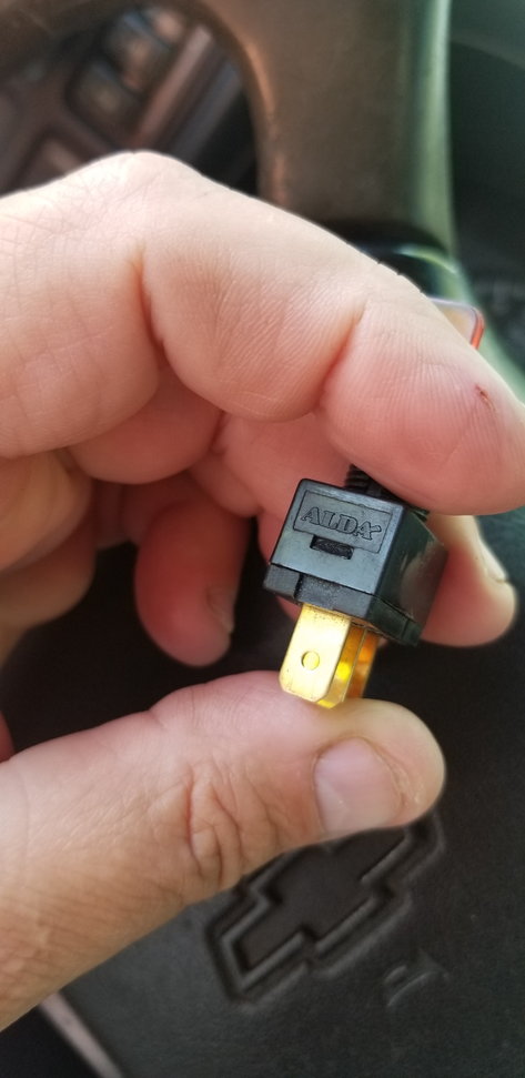
That 12v 20amp is the rating of the switch. Period.
The 12v 20 amp label, means that switch will handle the voltage and current listed.
Has ZERO to do with circuit protection.
We are not going to convince you that your switch is not a circuit protection. So take your switch and go directly between the positive and negative on your boat battery and see what happens.
Then do that with an ORIGINAL Formula helm switch. Your results will be different.
I have the Formula Factory wiring diagrams that show amp ratings on ALL the switches on the dash.
Scott at Formula tech support was kind enough to share them with me.
I have them for my old 1989 272SR1 and my 1993 419SR1. Both boats have circuit protection that ALJ has been talking about for Years. And has been kind enough to attempt explaining their function to you.
IF formula did not need circuit breaker (Circuit protection) at the switch, they probably would not have
spent the money to install them.
Since I re-wired my 272 left side through the galley to aft nav light due to a wiring fire.....
Trust alj when he takes the time to help others not aware of the pitfalls of working on wiring on Formula SR1 series.
08-10-2020 | 09:50 AM
#94
Registered
Joined: Sep 2008
Posts: 460
Likes: 31
That 12v 20amp is the rating of the switch. Period.
The 12v 20 amp label, means that switch will handle the voltage and current listed.
Has ZERO to do with circuit protection.
We are not going to convince you that your switch is not a circuit protection. So take your switch and go directly between the positive and negative on your boat battery and see what happens.
Then do that with an ORIGINAL Formula helm switch. Your results will be different.
I have the Formula Factory wiring diagrams that show amp ratings on ALL the switches on the dash.
Scott at Formula tech support was kind enough to share them with me.
I have them for my old 1989 272SR1 and my 1993 419SR1. Both boats have circuit protection that ALJ has been talking about for Years. And has been kind enough to attempt explaining their function to you.
IF formula did not need circuit breaker (Circuit protection) at the switch, they probably would not have
spent the money to install them.
Since I re-wired my 272 left side through the galley to aft nav light due to a wiring fire.....
Trust alj when he takes the time to help others not aware of the pitfalls of working on wiring on Formula SR1 series.
The 12v 20 amp label, means that switch will handle the voltage and current listed.
Has ZERO to do with circuit protection.
We are not going to convince you that your switch is not a circuit protection. So take your switch and go directly between the positive and negative on your boat battery and see what happens.
Then do that with an ORIGINAL Formula helm switch. Your results will be different.
I have the Formula Factory wiring diagrams that show amp ratings on ALL the switches on the dash.
Scott at Formula tech support was kind enough to share them with me.
I have them for my old 1989 272SR1 and my 1993 419SR1. Both boats have circuit protection that ALJ has been talking about for Years. And has been kind enough to attempt explaining their function to you.
IF formula did not need circuit breaker (Circuit protection) at the switch, they probably would not have
spent the money to install them.
Since I re-wired my 272 left side through the galley to aft nav light due to a wiring fire.....
Trust alj when he takes the time to help others not aware of the pitfalls of working on wiring on Formula SR1 series.
i just posted the rating. Ive been saying all along my switches are not breakers. 🤔
i have breakers.
Last edited by oconnor marine; 08-10-2020 at 09:53 AM.
08-10-2020 | 05:12 PM
#95
Registered
Joined: Oct 2002
Posts: 263
Likes: 11
From: nowhere
Read my post again.
I DID NOT QUOTE YOU.
All I did was comment that the 12V 20A pointed out on the switch was the switch rating.
Just humor me. Im old and tired.
my comment was meant as a FACT statement. Not a dispute.
In my experience, since you quoted yourself to being in the industry for 40+ years, sometimes we run across things that have defied logic.
If I�m wrong I will apologize and shut up. Just humor me and try an experiment WITH me.
I tried it on my two Formulas and would like to hear your experience with my test.
Select the switch at the helm to ON for your bilge pump. The pump should run.
Correct?
If it is running, hope it is.
Then with the bilge pump running, pull your circuit breaker under the seat that says Engine Bilge.
Does the pump continue to run?
Mine does.
Even when I Pull every circuit breaker on the panel in front of the engine compartment.
Now go under the dash and pull every circuit breaker under the dash.
Does the bilge pump continue to run?
IF it does, can you explain that logic?
12-17-2020 | 08:09 PM
#96
Registered
Joined: Oct 2002
Posts: 263
Likes: 11
From: nowhere
Has anyone tested my theory of power to the circuits on a formula instrument panel?
Plus.....
I have broken one of my last spare switches on the panel to run the bilge pump. 15A
Looking to replace switch and having difficulty finding lighted toggle switches previously displayed during this thread.
I would like a resource of those blue lighted toggle switches.
Void of discussion on IF the switches and circuit breaker type or not.
I can handle the issue with zero problems, once I find a source for the blue lighted toggles
12-18-2020 | 08:01 AM
#97
Registered
Joined: Jul 2009
Posts: 765
Likes: 291
From: USA, PA
with enough current, everything is a circuit breaker 
https://www.reddit.com/r/ANormalDayI.../safety_first/
https://www.reddit.com/r/ANormalDayI.../safety_first/
12-18-2020 | 12:27 PM
#98

Registered

Joined: Nov 2001
Posts: 208
Likes: 1
From: Mchenry,Ill.
Sabertoothsquirrel.... I had to laugh. Some folks just should not work on electrics. For them, I say, use the wire as the circuit breaker! Much cheaper for the materials than the way Formula engineered it. Laughing my a** off!
12-18-2020 | 02:00 PM
#99
Registered
Joined: Nov 2001
Posts: 208
Likes: 1
From: Mchenry,Ill.
Opie,
I looked again at the Formula wiring diagram supplied in my Formula Owners Information binder (F206LS ... should be the same as all others until you get to multiple bilge pump models). In diagram 206-95A on the far left of the diagram it shows the line for "constant power for bilge pump". It is a red wire with a brown trace line. On our boats of this era, there is an acrylic power post block on the hull side right next to each battery. Positive and negative from the battery goes to the appropriate post on those blocks and are NOT fused or circuit breakered. That Red/Brown wire is connected directly to the positive side of that power post (so not switched off when we turn the battery switches off). That wire leads directly to the bilge pump breaker at the rear of the cockpit which is usually under the rear seat. From that breaker the wire continues directly to the bilge pump float switch that was originally installed by Formula. That circuit provides "constant power" to the bilge pump that is automatically switched on in case water gets into the bilge and you aren't there to turn it on manually. (note that this circuit also supplies power to the Mercathode circuit breaker under the back seat if your boat is equipped with that option. The Mercathode must also operate even if you have the batteries switched off.)
As for the switch on the dash... That switch is for you to "manually" operate the bilge pump, regardless of whether the bilge FLOAT switch calls for the pump to turn on. You flip the switch= the pump turns on even if there's no water to pump. The power for that switch also comes off the same terminal on the bilge pump circuit breaker that the wire for the automatic float switch is getting power from. The "float" switch and the dash switch are wired "in parallel" so if either is switched on , the pump runs. The wire from the bilge breaker (rear) runs up through the instrument panel harness to the dash switch and is also supposed to be Red/ Brown. It goes through no other breakers and is wired directly to the dash switch and it returns back through the dash harness as a solid brown wire to go directly to the bilge pump ( not to the float switch this time ). Properly wired, the bilge pump will have three wires going to it. A red/brown from the float switch. A brown from the dash harness/dash switch. And a Black that goes directly to a ground through the bilge harness. Many people install new bilge pumps that have built in float switches and then get confused about how to wire three wires into the pump. I have also seen where "mechanics" have run a new wire to the breaker and are confused about which terminal or which side of the breaker is dead when the breaker is tripped off. Also check to make sure that a defective breaker wasn't replaced and the wires reinstalled all wrong completely. It isn't hard to screw it up because there are multiple Red/Brown wires at the rear circuit panel and one of them is always hot to the battery. Hell, it could have been screwed up by Formula at the factory when they built the boat.
Opie, if pulling that Bilge pump circuit breaker under your seat doesn't turn off the bilge pump, something is wrong. I know that you know 12 volt wiring so it shouldn't be hard to find the problem. Get out the test light! I had the same issue with my F402. Someone changed out the bilge pump on my boat and didn't understand (I'm guessing) why there were two wires powering the bilge pump. So ..... they just ran their own wire directly to the battery. No fuses, no circuit breaker, no fuss, no muss! Pigtail completely cut off near the pump and not wirenutted. They did the same thing with a blower. Maybe these "mechanics didn't know there was a second circuit breaker panel under the back seat? Maybe they were just idiots?I have no idea, but it caused a minor fire. It sounds like your fire was major. Take a look at your bilge pump wiring to see what got cut up and rewired.
Happy Holidays everyone!


