
Can some please explain Proper water flow?
SubscribeSB
Registered
close

Today
- Join DateNov 2004
- LocationOn A Dirt Floor
- Posts:14,154
-
Likes:4,969
-
Liked:3,714 Times in 1,696 Posts
Alpha system:
Outdrive pump, to transom thru small diameter (5/8” ?) hose. Inside boat, top of transom plate, there is a nipple fitting bolted to top. Hose connects to this, routes under motor on passenger side , just after motor mount it will go to power steering cooler. Hose goes from this up front if motor to the thermostat housing. Housing will prioritize water going to engine (recirculating pump) and the remainder to the exhaust. When engine thermostat opens, that water will also get routed to the exhaust. Since tstat prioritizes engine, more water will thereflow flow to engine with tstat open.
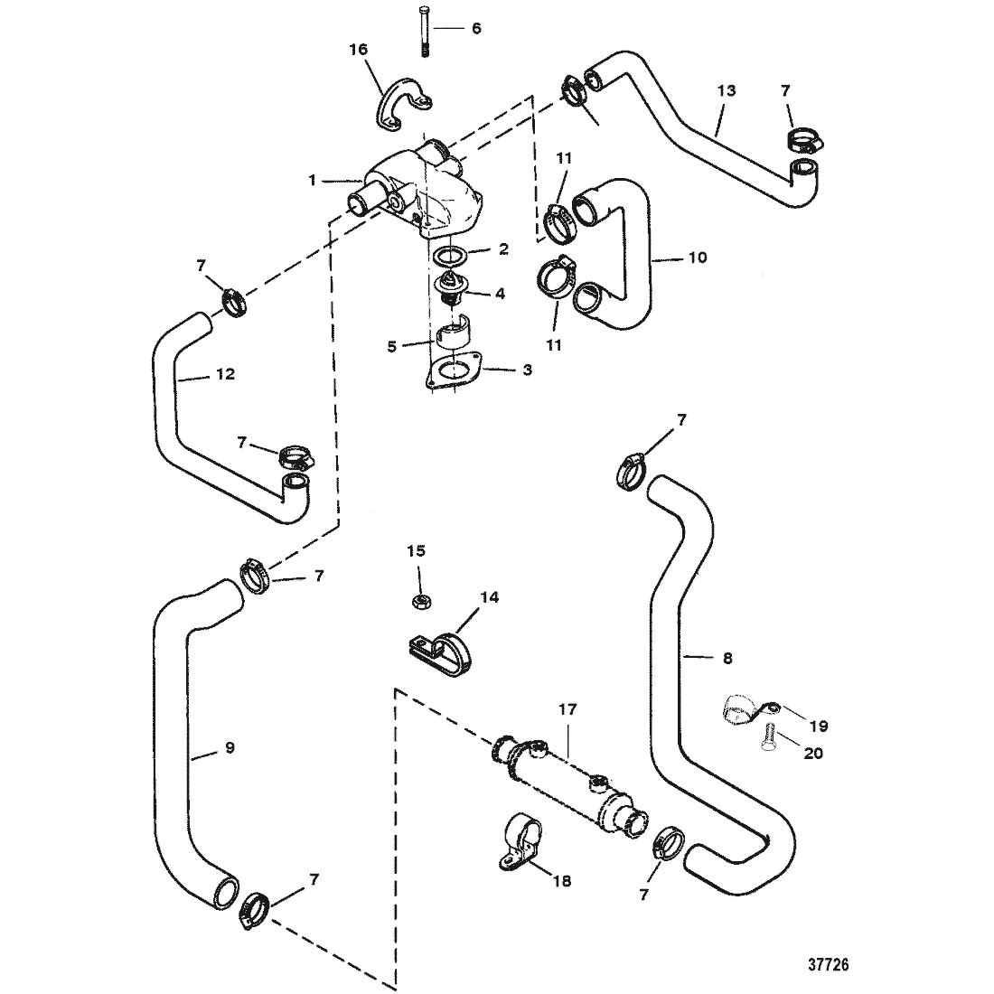
Outdrive pump, to transom thru small diameter (5/8” ?) hose. Inside boat, top of transom plate, there is a nipple fitting bolted to top. Hose connects to this, routes under motor on passenger side , just after motor mount it will go to power steering cooler. Hose goes from this up front if motor to the thermostat housing. Housing will prioritize water going to engine (recirculating pump) and the remainder to the exhaust. When engine thermostat opens, that water will also get routed to the exhaust. Since tstat prioritizes engine, more water will thereflow flow to engine with tstat open.

Once water enters the y pipe it will take the path of least resistance to exit the boat depending on boat angle, drive angle, pressure, etc. The exit locations are the 2 holes on the transom assembly and through the prop.
SB
Registered
close
Today
- Join DateNov 2004
- LocationOn A Dirt Floor
- Posts:14,154
-
Likes:4,969
-
Liked:3,714 Times in 1,696 Posts
Found a water flow chart that shows what I explained: (most older engines don’t have a fuel cooler, but have ps cooler where fuel cooler is in the chart)

Quote:
this information is perfect. It gives me something to focus on and track down. Before this I was at a loss. Thank you so much Originally Posted by SB
Found a water flow chart that shows what I explained: (most older engines don’t have a fuel cooler, but have ps cooler where fuel cooler is in the chart)
sutphen 30
Registered
close
Yesterday
- Join DateJan 2006
- Locationtaxachusetts
- Posts:3,601
-
Likes:1,027
-
Liked:1,169 Times in 605 Posts
also,,take close attention to the thermostat,,you wouldn't be the first person to install it wrong.
Quote:
I'm almost positive I had the spring facing down. And I know the plastic retainer is installed right. I made sure the ports wasn't blocked by the plastic retainer and besides that, it's notched and grooved to only go one way Originally Posted by sutphen 30
also,,take close attention to the thermostat,,you wouldn't be the first person to install it wrong.
outonsafari
Registered
close

05-15-2026
- Join DateMay 2009
- Posts:1,942
-
Likes:171
-
Liked:527 Times in 274 Posts

up there on the risers are the rubber boots that connect to the Y pipe, up near the top of the Y pipe are some flappers on each side.
Every once in a while they deteriorate or fail in some kinda way in which all or part of them end up as far as the drive.
only way to find out is remove the boots and scope the Y pipe, next would be to pull and split the drive.
Some shop putting in an impellor doesn't mean anyone looked any deeper if there was no complaint
New flappers doesn't mean the old ones or part of the old ones aren't jammed up somewhere down stream.

