

Do Perko battery selector switches go bad?
 07-01-2020 | 08:40 PM
#1
Thread Starter
Registered

Joined: Jun 2007
Posts: 111
Likes: 13
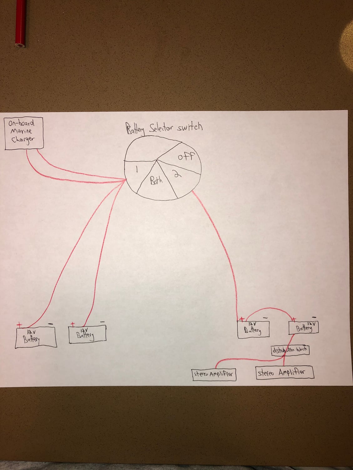
All my electronics, accessories, engine etc, work no matter if the battery selector switch is on 1, both, 2 or off. So it doesn�t seem like the switch is functioning at all. Below is a diagram of how it is connected. The boat does have a onboard marine charger with two positive wires coming off it, presumably for two different �banks�. I�m not sure if the charger is contributing to the switch not functioning, or if the switch went bad, or if the switch is wired incorrectly. FWIW, the onboard charger shows the exact same voltage for both banks. Any input would be appreciated.
 07-02-2020 | 05:46 AM
#2
Registered

Joined: Oct 2005
Posts: 1,074
Likes: 251
From: Waldorf, Md
A switch can most certainly fail, just like any other mechanical device. It should be pretty easy to troubleshoot if you have a multi meter and a little electrical knowledge.
Your wiring diagram really makes no sense to me but all of the Perko wiring diagrams are on their web site so you should be able to determine if it is wired correctly. Here is a link to what appears to be the most common switch:
https://www.perko.com/images/catalog...(8500INS1).pdf
A picture of the back of the switch showing your connections would help. It looks like your sound system is connected directly to the batteries without going through the switch.
Hope this helps,
07-02-2020 | 08:15 AM
#3
Thread Starter
Registered
Joined: Jun 2007
Posts: 111
Likes: 13
The wiring at the back of the switch is as shown in my diagram. There are positive cables from two of the batteries on the left-hand side of the diagram, including two positive leads from the onboard battery charger that go to terminal number 1 of the switch. And then there is one single positive wire from the sound system batteries that is attached to terminal number 2 on the switch. Hopefully that helps clarify. What I�m wondering is if the connections are correctly made at the battery selector switch.
FYI, I did look at Perko�s website but they do not have a wiring diagram for my specific situation (single engine boat, three �banks� of batteries, and an onboard marine battery charger).
Thanks in advance to all the electrical gurus out there!
FYI, I did look at Perko�s website but they do not have a wiring diagram for my specific situation (single engine boat, three �banks� of batteries, and an onboard marine battery charger).
Thanks in advance to all the electrical gurus out there!
07-02-2020 | 09:05 AM
#4
Registered
Joined: Oct 2005
Posts: 1,074
Likes: 251
From: Waldorf, Md
If you turn the switch off, what voltage are you reading at the "Common" terminal on the switch ? It should be "Zero"
07-02-2020 | 09:44 AM
#5
Registered
Joined: Jul 2007
Posts: 3,336
Likes: 857
Your diagram is isolating the onboard charger to the two banks of batteries only - left two batteries or right two by back feeding the voltage trough the switch (battery charger depending on model should have a lead to each battery as its probably designed for servicing 2 batteries utilizing a common ground wire). It would be much more specific to have the batteries charged/monitored through a battery isolator and having two battery switches to provide power to the loads - one for cranking the engines and one for shutting down the power from the house batteries to the stereo amplifiers.
If you onboard charger is a "smart" charger, the output could be less amp than what is expected as you have both leads providing power to the same contact point on the battery switch.
http://www.emarineinc.com/categories/Battery-Isolators
If you onboard charger is a "smart" charger, the output could be less amp than what is expected as you have both leads providing power to the same contact point on the battery switch.
http://www.emarineinc.com/categories/Battery-Isolators
 07-02-2020 | 02:44 PM
#8
Registered
Joined: Nov 2004
Posts: 14,108
Likes: 3,694
From: On A Dirt Floor
Op�s Amps are connected to their batteries directly at a post of switch. How does the switch disconnect this currently? It doesn�t.
t�s not clear but i think op may be confused with how the switches work and thus how should be wired.
t�s not clear but i think op may be confused with how the switches work and thus how should be wired.
07-02-2020 | 03:33 PM
#9
Thread Starter
Registered
Joined: Jun 2007
Posts: 111
Likes: 13
OP Is definitely seeking clarification. this is how it was wired by the previous owner. I�m not sure it�s correct. And I am looking for the correct way to wire this in order to utilize the switch, and the onboard battery charger to charge all the batteries.


