

Sticky?? Cam overlap degrees for marine cam selection
 09-03-2025 | 12:52 AM
#41
Registered


Joined: Aug 2019
Posts: 1,249
Likes: 420
From: BC
Okay, good thing about posting pics�. Those are the really old style logs� so I have no idea, at least they pointed down. More common style are the center rise where the risers go up and then down a little bit and those need extensions. The old style is even more restrictive as far as exhaust gas but I have no idea how much I never dealt with them before. Maybe the guys that dealt with the old stuff what time in?
2.2cfm/hp for zero backpressure.
As an example, the newer BBC Merc Cast exh manifolds will support 425hp unrestricted. ( to through hulls and not prop)
I have a set of the older style on a 280 TRS SBC to tear down, I'll see if I can measure them up.
 09-03-2025 | 11:04 AM
#42
Registered
Joined: Aug 2025
Posts: 34
Likes: 43
Thanks for the suggestion powerboatr . Tbh, I have been worried that I'll need to rework the exhaust system.
Tartilla Doing rough calcs, the motor will be exhausting about 850cfm at 6000rpm. Based on your experience, would replacing the stock manifolds with something like Powerboatr suggested be enough or will the sterndrive still be the restriction point? This is a family boat more than a race boat, so keeping it on the quieter side is pretty important (no thru-hull).
Tartilla Doing rough calcs, the motor will be exhausting about 850cfm at 6000rpm. Based on your experience, would replacing the stock manifolds with something like Powerboatr suggested be enough or will the sterndrive still be the restriction point? This is a family boat more than a race boat, so keeping it on the quieter side is pretty important (no thru-hull).
09-03-2025 | 01:05 PM
#43
Registered

Joined: Nov 2004
Posts: 14,152
Likes: 3,712
From: On A Dirt Floor
If you want to keep your exhaust underwater and thus quiet but do not want to put it through the outdrive you can get an exhaust tube versus exhaust bellows. The tube does not connect without drive so literally it�s a section of five or 6 inch tubber that connect to gimbal but exhausts into lake/ocean before the drive.

09-05-2025 | 05:08 PM
#44
Registered
Joined: Aug 2019
Posts: 1,249
Likes: 420
From: BC
Thanks for the suggestion powerboatr . Tbh, I have been worried that I'll need to rework the exhaust system.
Tartilla Doing rough calcs, the motor will be exhausting about 850cfm at 6000rpm. Based on your experience, would replacing the stock manifolds with something like Powerboatr suggested be enough or will the sterndrive still be the restriction point? This is a family boat more than a race boat, so keeping it on the quieter side is pretty important (no thru-hull).
Tartilla Doing rough calcs, the motor will be exhausting about 850cfm at 6000rpm. Based on your experience, would replacing the stock manifolds with something like Powerboatr suggested be enough or will the sterndrive still be the restriction point? This is a family boat more than a race boat, so keeping it on the quieter side is pretty important (no thru-hull).
How did you deternine 850cfm at 6000rpm with a 406SBC?
My calcs:
406cid @6000 rpm (3000 pwr strokes) � 1728= 705cfm
Peak Vol Eff comes in at peak TQ. As rpm increases and you hit peak power, airflow is reduced.
It's possible you won't even make 100% VE at peak TQ.
Airflow at peak TQ around 4500 wpild be in the 500cfm range.
Airflow at 6000rpm will be in the 600cfm range.
600cfm�2= 300cfm per exh man.
115cfm/sq" you would require 2.6sq" exhaust cross sectional area on each side for minimal flow loss.
You would need 5.2sq"( 2.6" diameter pipe) to flow your 600cfm at 6000. Approx.
I should put a Bravo drive on a flow bench for fun. Include the Y pipe
These numbers are for unrestricted. Keep in mind...adding water flow massively affects airflow.
With a prop exhaust system: moving 60mph = 5280ft/min.
5" prop exh diameter (drive bullet) displaces about 20" square. At 5280'/min it's about 61 cfm water displacement. Your exhaust 600cfm at 60mph (theoretical), still has backpressure just being under water, despite the drive moving etc.
09-06-2025 | 09:47 AM
#45
Registered
Joined: Aug 2025
Posts: 34
Likes: 43
Regarding displacement, I've had a slight change of plans. My builder says he can build a 427ci that will still accommodate a standard base circle cam, so I am leaning that direction. I hope to get to the low to mid 500HP/TQ range.
I used an equation that I found online, but I can't seem to track it down now. In any case, I trust your numbers over what I found. I have a lead on a set of CMI E-tops, so that would reduce some of the back pressure. The next restriction point seems to be the bottom of the Y pipe where it turns a sharp 180deg into the transom. From what I see, each leg of the Y pipe splits internally with the smaller channels running to the bottom two ports at the transom. These vents directly to the atmosphere. I assume this is for idle or low speed exhaust, and then the majority of the exhaust flows through the tube into the sterndrive? Has anyone tried merging these and porting the back side of the transom so the exhaust pressure is more equalized between the three ports?
I have also read some threads where folks say that the prop and stern drive create a partial vacuum that draws the exhaust into it. They argue that it is actually better than exhausting to atmosphere at the transom. What are your thoughts?
Last edited by OGHallett; 09-06-2025 at 09:53 AM.
09-06-2025 | 12:02 PM
#46
Registered
Joined: Aug 2019
Posts: 1,249
Likes: 420
From: BC
Regarding displacement, I've had a slight change of plans. My builder says he can build a 427ci that will still accommodate a standard base circle cam, so I am leaning that direction. I hope to get to the low to mid 500HP/TQ range.
I used an equation that I found online, but I can't seem to track it down now. In any case, I trust your numbers over what I found. I have a lead on a set of CMI E-tops, so that would reduce some of the back pressure. The next restriction point seems to be the bottom of the Y pipe where it turns a sharp 180deg into the transom. From what I see, each leg of the Y pipe splits internally with the smaller channels running to the bottom two ports at the transom. These vents directly to the atmosphere. I assume this is for idle or low speed exhaust, and then the majority of the exhaust flows through the tube into the sterndrive? Has anyone tried merging these and porting the back side of the transom so the exhaust pressure is more equalized between the three ports?
I have also read some threads where folks say that the prop and stern drive create a partial vacuum that draws the exhaust into it. They argue that it is actually better than exhausting to atmosphere at the transom. What are your thoughts?
I used an equation that I found online, but I can't seem to track it down now. In any case, I trust your numbers over what I found. I have a lead on a set of CMI E-tops, so that would reduce some of the back pressure. The next restriction point seems to be the bottom of the Y pipe where it turns a sharp 180deg into the transom. From what I see, each leg of the Y pipe splits internally with the smaller channels running to the bottom two ports at the transom. These vents directly to the atmosphere. I assume this is for idle or low speed exhaust, and then the majority of the exhaust flows through the tube into the sterndrive? Has anyone tried merging these and porting the back side of the transom so the exhaust pressure is more equalized between the three ports?
I have also read some threads where folks say that the prop and stern drive create a partial vacuum that draws the exhaust into it. They argue that it is actually better than exhausting to atmosphere at the transom. What are your thoughts?
BBC vs SBC is always a stronger option. Easier to find exh manifolds as well.
A 427 SBC for marine at 500hp is on the ragged edge. Are you using an aftermarket block? The factory 400 blocks can split apart at the webs. A BBC with aluminum heads is at SBC weight area.
Is there any reason you wouldn't go BBC? They're far more common, and the cam required to make your 500hp will be far easier for everything you want to do.
500hp at marine rpm is harder than in a car/truck.
Depending on how much room you have under your transom, you could fabricate a transverse stainless wet muffler and exit out of the transom. Or put a muffler on the tails outside of the transom. At 500hp you're looking at 4.75sq" per side for flow.
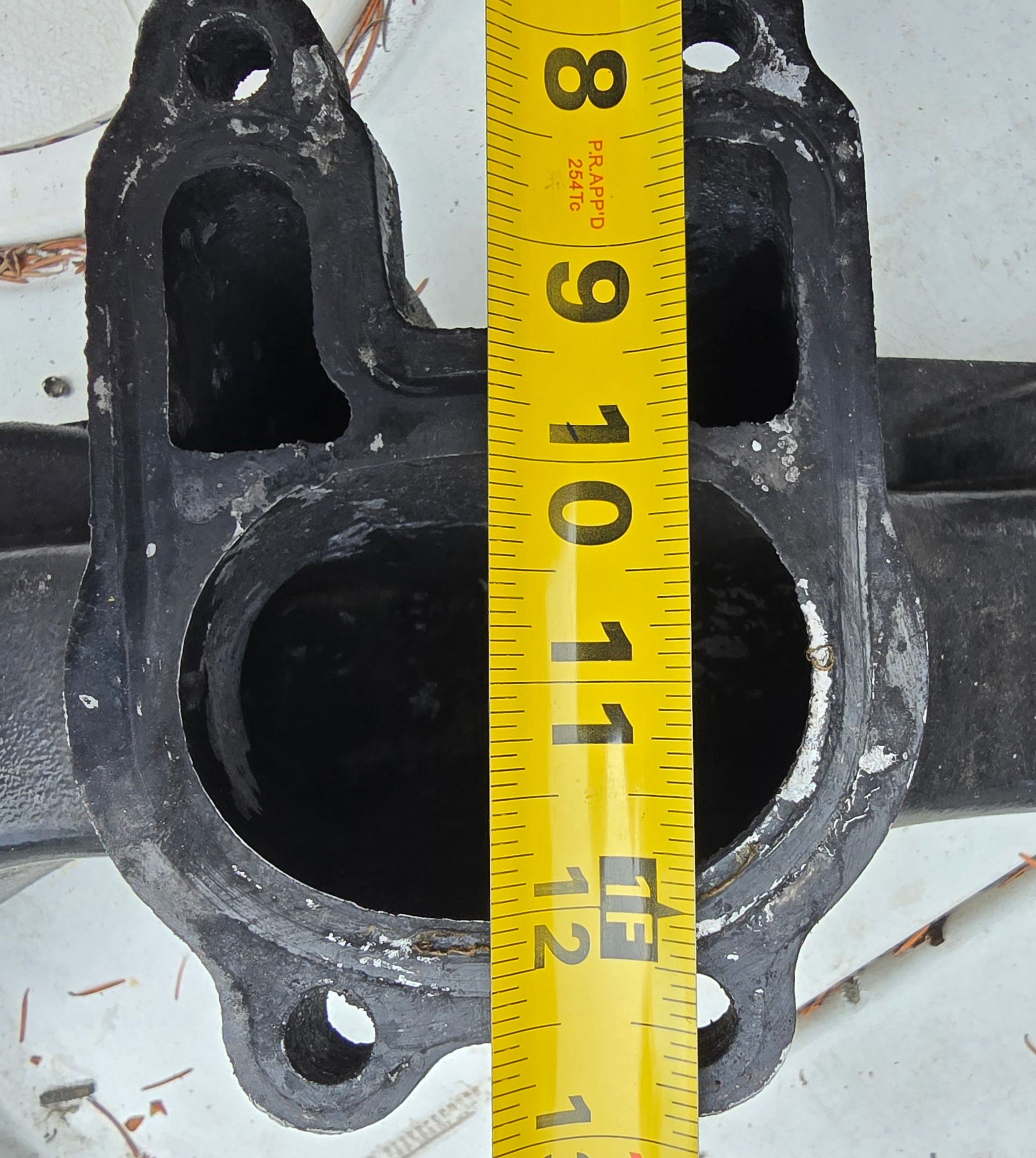
I have a loose Bravo1 Y pipe...I'll take a photo and measurements later today.
09-06-2025 | 12:15 PM
#47
Registered
Joined: Aug 2019
Posts: 1,249
Likes: 420
From: BC
Regarding displacement, I've had a slight change of plans. My builder says he can build a 427ci that will still accommodate a standard base circle cam, so I am leaning that direction. I hope to get to the low to mid 500HP/TQ range.
I used an equation that I found online, but I can't seem to track it down now. In any case, I trust your numbers over what I found. I have a lead on a set of CMI E-tops, so that would reduce some of the back pressure. The next restriction point seems to be the bottom of the Y pipe where it turns a sharp 180deg into the transom. From what I see, each leg of the Y pipe splits internally with the smaller channels running to the bottom two ports at the transom. These vents directly to the atmosphere. I assume this is for idle or low speed exhaust, and then the majority of the exhaust flows through the tube into the sterndrive? Has anyone tried merging these and porting the back side of the transom so the exhaust pressure is more equalized between the three ports?
I have also read some threads where folks say that the prop and stern drive create a partial vacuum that draws the exhaust into it. They argue that it is actually better than exhausting to atmosphere at the transom. What are your thoughts?
I used an equation that I found online, but I can't seem to track it down now. In any case, I trust your numbers over what I found. I have a lead on a set of CMI E-tops, so that would reduce some of the back pressure. The next restriction point seems to be the bottom of the Y pipe where it turns a sharp 180deg into the transom. From what I see, each leg of the Y pipe splits internally with the smaller channels running to the bottom two ports at the transom. These vents directly to the atmosphere. I assume this is for idle or low speed exhaust, and then the majority of the exhaust flows through the tube into the sterndrive? Has anyone tried merging these and porting the back side of the transom so the exhaust pressure is more equalized between the three ports?
I have also read some threads where folks say that the prop and stern drive create a partial vacuum that draws the exhaust into it. They argue that it is actually better than exhausting to atmosphere at the transom. What are your thoughts?
BBC vs SBC is always a stronger option. Easier to find exh manifolds as well.
A 427 SBC for marine at 500hp is on the ragged edge. Are you using an aftermarket block? The factory 400 blocks can split apart at the webs. A BBC with aluminum heads is at SBC weight area.
Is there any reason you wouldn't go BBC? They're far more common, and the cam required to make your 500hp will be far easier for everything you want to do.
500hp at marine rpm is harder than in a car/truck.
Depending on how much room you have under your transom, you could fabricate a transverse stainless wet muffler and exit out of the transom. Or put a muffler on the tails outside of the transom. At 500hp you're looking at 4.75sq" per side for flow.
I have a loose Bravo1 Y pipe...I'll take a photo and measurements later today.
09-06-2025 | 12:58 PM
#48
Registered
Joined: Aug 2025
Posts: 34
Likes: 43
I did not read the last portion of your post well enough Those calcs make it very clear. Thanks for offering to measure the Y pipe.
And yes, as of now the engine will be built using a Dart SHP block, AFR 210 heads, forged internals, etc. It's not a race boat, so I don't plan to run the motor at full throttle for more than 30-60 seconds at a time.
I originally planned to use all the existing auxiliary components and drop in the new engine. But, this project has grown in scope quite a bit so a BBC is not as far out of consideration as it originally was. I do think changing to a big block would require a change to interior layout of the boat, mainly in height and length of the engine cover, so that is not ideal.
Those calcs make it very clear. Thanks for offering to measure the Y pipe.And yes, as of now the engine will be built using a Dart SHP block, AFR 210 heads, forged internals, etc. It's not a race boat, so I don't plan to run the motor at full throttle for more than 30-60 seconds at a time.
I originally planned to use all the existing auxiliary components and drop in the new engine. But, this project has grown in scope quite a bit so a BBC is not as far out of consideration as it originally was. I do think changing to a big block would require a change to interior layout of the boat, mainly in height and length of the engine cover, so that is not ideal.
09-06-2025 | 02:12 PM
#49
Registered
Joined: Aug 2019
Posts: 1,249
Likes: 420
From: BC
Projects have a tendency to morph into a new reality...
Keep your mission in mind. Often difficult to do. Mission creep is the reality of life, we need to be vigilant. If you want a different outcome/intent...change your mission.
BBCs are only about 1.85" longer...but it's the extra height that makes the issues to fit under a housing.
BBC pan to intake man flange is 11", SBC is 10". Plus intake man differences.
Aftermarket SBC block would be the way for the 427.

You have about 50% of the flow area you require for your HP goals. Somethings 'gotta give.
Keep your mission in mind. Often difficult to do. Mission creep is the reality of life, we need to be vigilant. If you want a different outcome/intent...change your mission.
BBCs are only about 1.85" longer...but it's the extra height that makes the issues to fit under a housing.
BBC pan to intake man flange is 11", SBC is 10". Plus intake man differences.
Aftermarket SBC block would be the way for the 427.
You have about 50% of the flow area you require for your HP goals. Somethings 'gotta give.
09-06-2025 | 05:17 PM
#50
Registered
Joined: Aug 2025
Posts: 34
Likes: 43
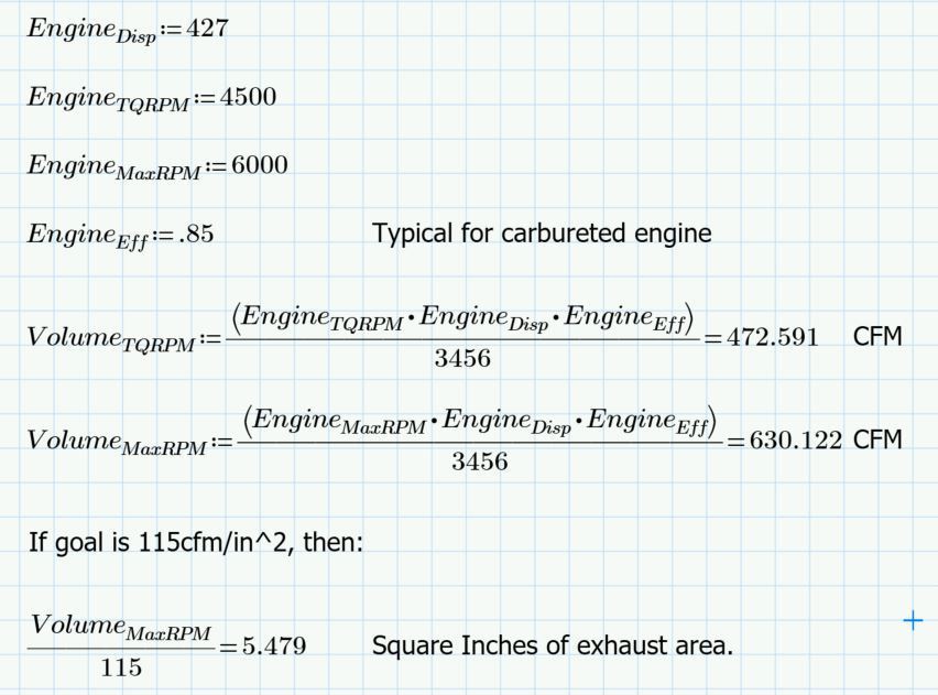
These photos were very helpful. I ran the math and it lines up with what you had previously posted:
I also roughly modeled the opening in cad software to estimate cross sectional area.
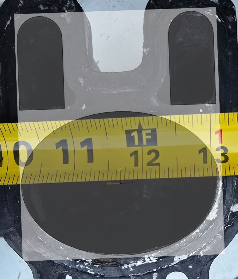
If the two smaller openings are included, the cross sectional area is just shy of 6in^2. The calcs show that the opening would need to be about 5.5in^2 at 85% efficiency and 6.5in^2 at 100% efficiency. Does this look correct to you? If so, it doesn't seem totally unreasonable.
I also roughly modeled the opening in cad software to estimate cross sectional area.
If the two smaller openings are included, the cross sectional area is just shy of 6in^2. The calcs show that the opening would need to be about 5.5in^2 at 85% efficiency and 6.5in^2 at 100% efficiency. Does this look correct to you? If so, it doesn't seem totally unreasonable.
Last edited by OGHallett; 09-06-2025 at 06:25 PM.

