

40' Outlaw Upgrades - Twin 900Sc to 1000hp Duramax Diesels
 05-03-2021, 06:37 AM
#1181
Registered
Thread Starter
Ok 16hrs driving and find myself 1000 miles away from the project again. Setting here in same location that I was drawing up extension boxes in CAD exactly 5yrs ago. Only thing changed is my recliner. Wife thew out my old one while I was away in Florida... I'm sure gonna miss her.. ")
What we know, and why nothing we have or can purchase off the shelf will work to just bolt up these 6's.
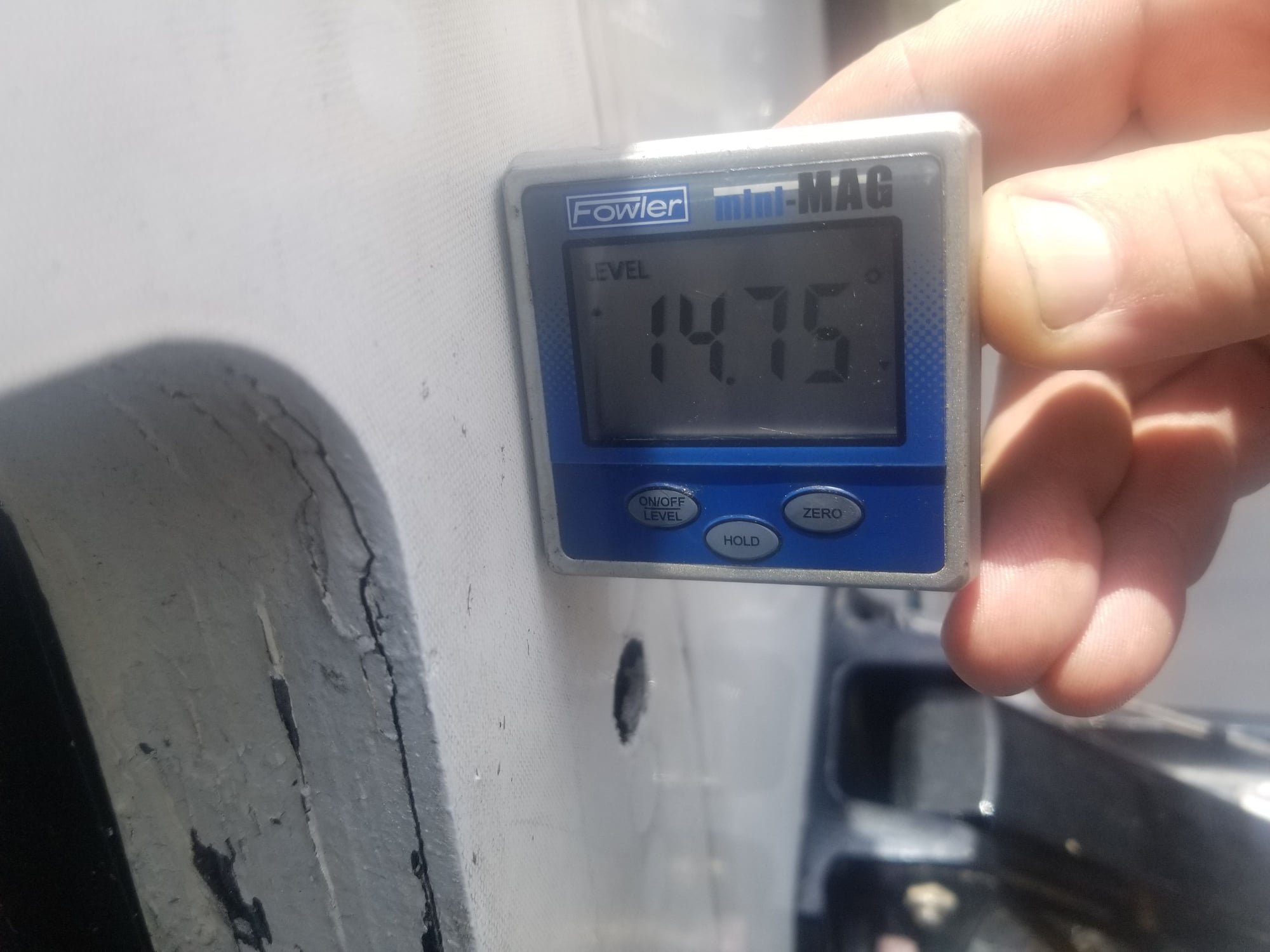
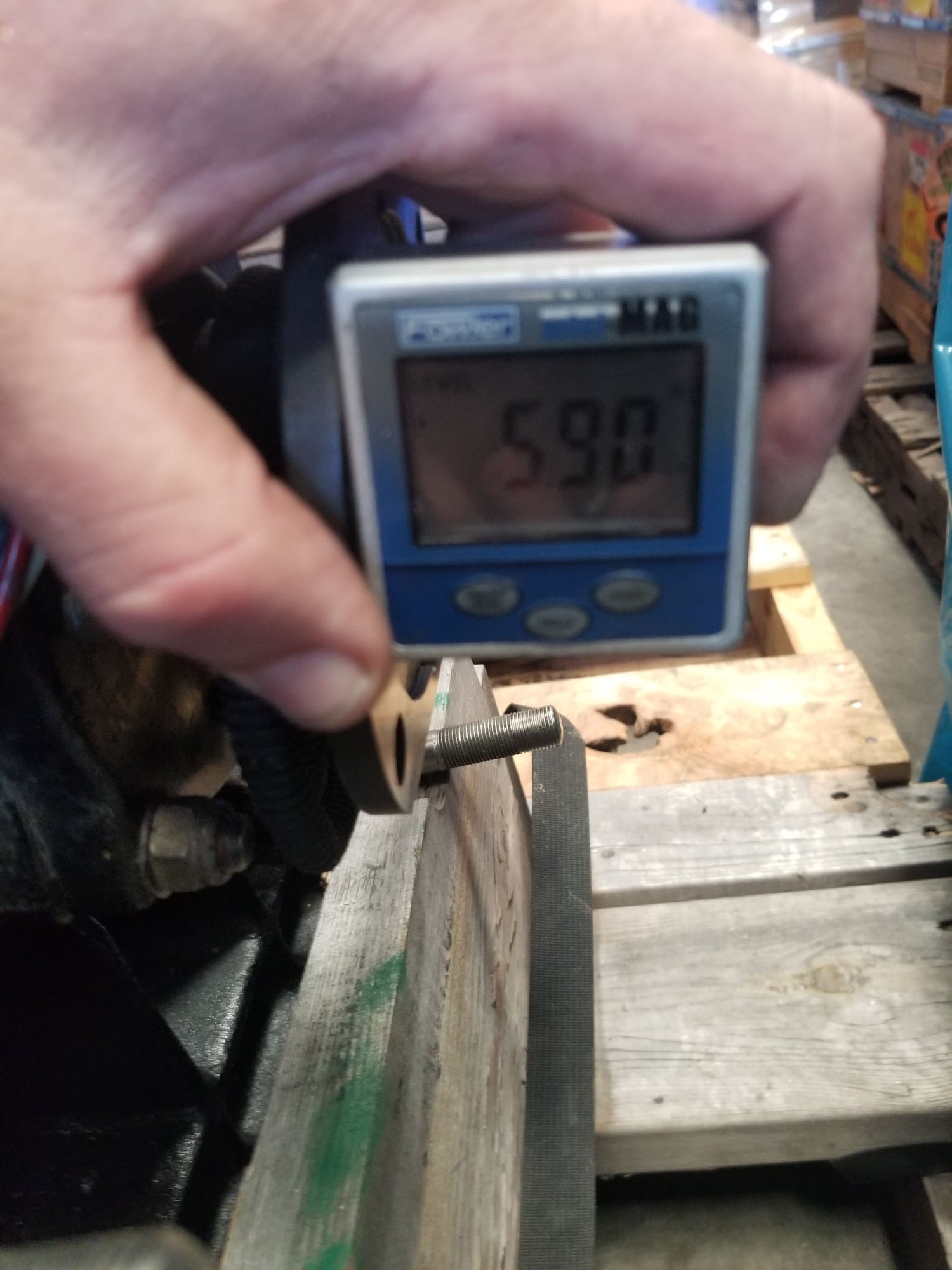
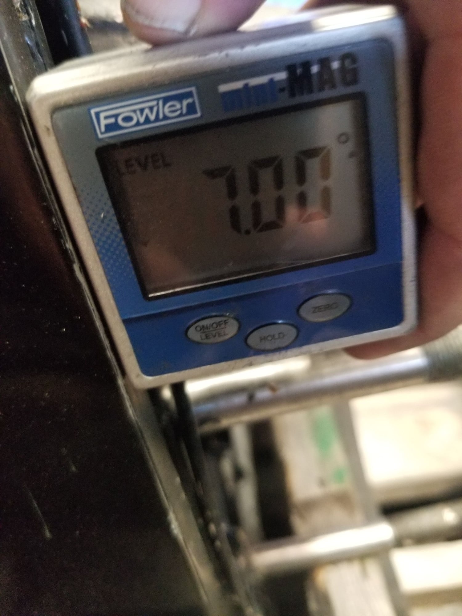
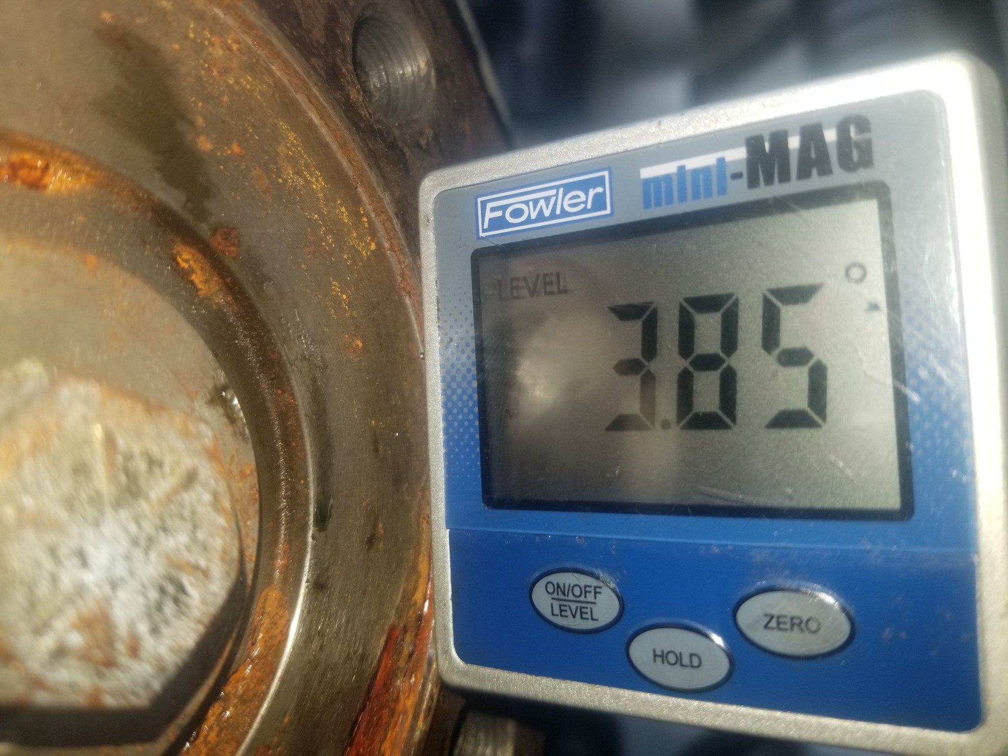
1st, this Baja has a 15� transom angle, "standard" and Merc #6 transom assembly is 13� as seen when comparing the angles between our new Merc driveshaft flange to transom assembly edge faces with a meter below. But this boat came factory with 6's and no wedge plates. Not sure how that worked since I never rode in it before we started the project. But guessing it was not an issue since a Plug-In style 6 uses a double cardan driveshaft. Thus allowing for higher acceptable operating angles.
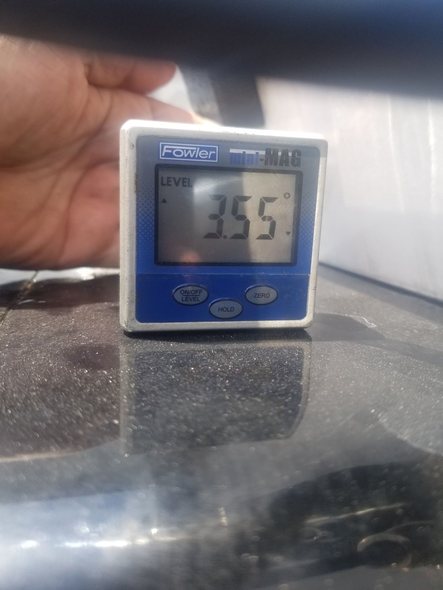
2nd, to clear our deep sump oil pans and help raise our previous drive height, we [Will Smith and I] setup the diesel drivetrain with -3.5� down angle. This "experiment" was to land our crankshaft centerline, and their 250lbs of rotating mass per engine as close to horizontal at running speeds as possible. Something not common to performance boats, but seems to have paid off in stability. Imagine a seakeeper gyro for longitudinal stability. At 3-4000R's she is on rails no matter the water conditions. Zero chine walking observed, tracks arrow straight, and carries the bow nicely above 75mph.
3rd, maximum acceptable "driveline" [no double cardan driveshaft] phase angle is 1� according to: https://www.therangerstation.com/tec...onangles.shtml
Ideally, the operating angles on each end of the driveshaft should be equal to or within 1 degree of each other, have a 3* degree maximum operating angle and have at least 1/2 of a degree continuous operating angle.
Which was all calculated and laid out exactly to fit the Weismann drives, that just so happens to have a 6" drop box inside the transom assembly. While the lower units shares similar 15" drop input to propshaft as a Merc. Landing us about 6" lower now on our new transom assembly U-joint flange, and 5.5� outa phase.
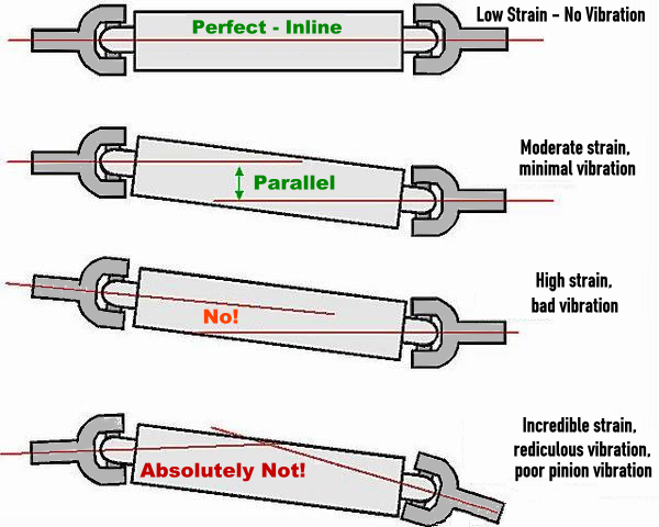
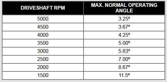
Confused yet? Sure as hell know I am... We haven't even got around to calculating where the propshaft height lands in all this yet. But just bolting up a driveshaft using the extension box we tested above, would end up looking like the bottom example below.. And with shorter driveshafts now, our Max Operating Angle must land under 4� to avoid eating U-Joints. This should be fun to draw up..
Here is a good video I found that demonstrates all there principles above. Doesn't dive into the double cardan setup, which without that, there would be no trimable IO setup on boats, or short front shaft 4x4 trucks. But we aren't going that route for our main driveline driveshafts if at all possible. Don't know where we'll land yet, but that 3-3/4" propshaft height difference observed a few posts above, just got eliminated.

What we know, and why nothing we have or can purchase off the shelf will work to just bolt up these 6's.
1st, this Baja has a 15� transom angle, "standard" and Merc #6 transom assembly is 13� as seen when comparing the angles between our new Merc driveshaft flange to transom assembly edge faces with a meter below. But this boat came factory with 6's and no wedge plates. Not sure how that worked since I never rode in it before we started the project. But guessing it was not an issue since a Plug-In style 6 uses a double cardan driveshaft. Thus allowing for higher acceptable operating angles.
2nd, to clear our deep sump oil pans and help raise our previous drive height, we [Will Smith and I] setup the diesel drivetrain with -3.5� down angle. This "experiment" was to land our crankshaft centerline, and their 250lbs of rotating mass per engine as close to horizontal at running speeds as possible. Something not common to performance boats, but seems to have paid off in stability. Imagine a seakeeper gyro for longitudinal stability. At 3-4000R's she is on rails no matter the water conditions. Zero chine walking observed, tracks arrow straight, and carries the bow nicely above 75mph.
3rd, maximum acceptable "driveline" [no double cardan driveshaft] phase angle is 1� according to: https://www.therangerstation.com/tec...onangles.shtml
Ideally, the operating angles on each end of the driveshaft should be equal to or within 1 degree of each other, have a 3* degree maximum operating angle and have at least 1/2 of a degree continuous operating angle.
Which was all calculated and laid out exactly to fit the Weismann drives, that just so happens to have a 6" drop box inside the transom assembly. While the lower units shares similar 15" drop input to propshaft as a Merc. Landing us about 6" lower now on our new transom assembly U-joint flange, and 5.5� outa phase.
Confused yet? Sure as hell know I am... We haven't even got around to calculating where the propshaft height lands in all this yet. But just bolting up a driveshaft using the extension box we tested above, would end up looking like the bottom example below.. And with shorter driveshafts now, our Max Operating Angle must land under 4� to avoid eating U-Joints. This should be fun to draw up..
Here is a good video I found that demonstrates all there principles above. Doesn't dive into the double cardan setup, which without that, there would be no trimable IO setup on boats, or short front shaft 4x4 trucks. But we aren't going that route for our main driveline driveshafts if at all possible. Don't know where we'll land yet, but that 3-3/4" propshaft height difference observed a few posts above, just got eliminated.
Last edited by kidturbo; 05-03-2021 at 06:46 AM.

The following 4 users liked this post by kidturbo:
05-03-2021, 10:48 AM
#1182
Ok 16hrs driving and find myself 1000 miles away from the project again. Setting here in same location that I was drawing up extension boxes in CAD exactly 5yrs ago. Only thing changed is my recliner. Wife thew out my old one while I was away in Florida... I'm sure gonna miss her..
What we know, and why nothing we have or can purchase off the shelf will work to just bolt up these 6's.
1st, this Baja has a 15� transom angle, "standard" and Merc #6 transom assembly is 13� as seen when comparing the angles between our new Merc driveshaft flange to transom assembly edge faces with a meter below. But this boat came factory with 6's and no wedge plates. Not sure how that worked since I never rode in it before we started the project. But guessing it was not an issue since a Plug-In style 6 uses a double cardan driveshaft. Thus allowing for higher acceptable operating angles.
2nd, to clear our deep sump oil pans and help raise our previous drive height, we [Will Smith and I] setup the diesel drivetrain with -3.5� down angle. This "experiment" was to land our crankshaft centerline, and their 250lbs of rotating mass per engine as close to horizontal at running speeds as possible. Something not common to performance boats, but seems to have paid off in stability. Imagine a seakeeper gyro for longitudinal stability. At 3-4000R's she is on rails no matter the water conditions. Zero chine walking observed, tracks arrow straight, and carries the bow nicely above 75mph.
3rd, maximum acceptable "driveline" [no double cardan driveshaft] phase angle is 1� according to: https://www.therangerstation.com/tec...onangles.shtml
Ideally, the operating angles on each end of the driveshaft should be equal to or within 1 degree of each other, have a 3* degree maximum operating angle and have at least 1/2 of a degree continuous operating angle.
Which was all calculated and laid out exactly to fit the Weismann drives, that just so happens to have a 6" drop box inside the transom assembly. While the lower units shares similar 15" drop input to propshaft as a Merc. Landing us about 6" lower now on our new transom assembly U-joint flange, and 5.5� outa phase.
Confused yet? Sure as hell know I am... We haven't even got around to calculating where the propshaft height lands in all this yet. But just bolting up a driveshaft using the extension box we tested above, would end up looking like the bottom example below.. And with shorter driveshafts now, our Max Operating Angle must land under 4� to avoid eating U-Joints. This should be fun to draw up..
Here is a good video I found that demonstrates all there principles above. Doesn't dive into the double cardan setup, which without that, there would be no trimable IO setup on boats, or short front shaft 4x4 trucks. But we aren't going that route for our main driveline driveshafts if at all possible. Don't know where we'll land yet, but that 3-3/4" propshaft height difference observed a few posts above, just got eliminated.
https://youtu.be/Idk3BVDVHq4
05-03-2021, 03:06 PM
#1183
Registered
Have you think about CV joints? They have no angle speed error, or whatever it real name is in English, so you can run it not parallel.
I will use these in my Fountain. Transmash will make 6000lb/ft torque, of course split half when overdrive 1:1.8 and again split half to two drives but there is 1500lb/ft left torture CV joints and 934 Crmo joints should keep alive.
https://www.racereadyproducts.com/cv...934-cv-joints/
CV joints have axial play so you don't need spline slide in cardan.
05-03-2021, 05:36 PM
#1184
Registered
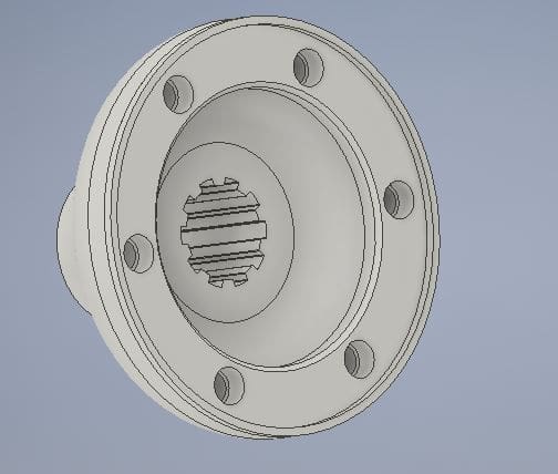
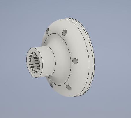
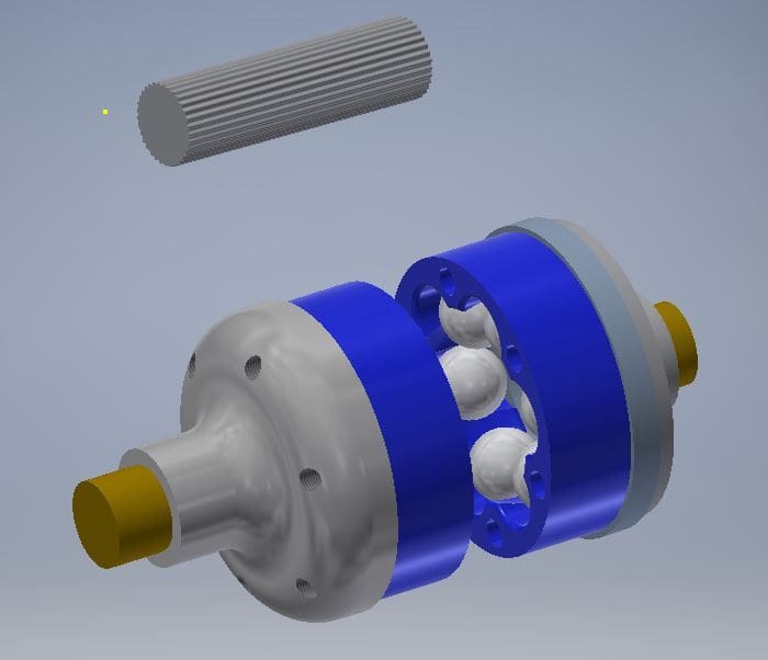
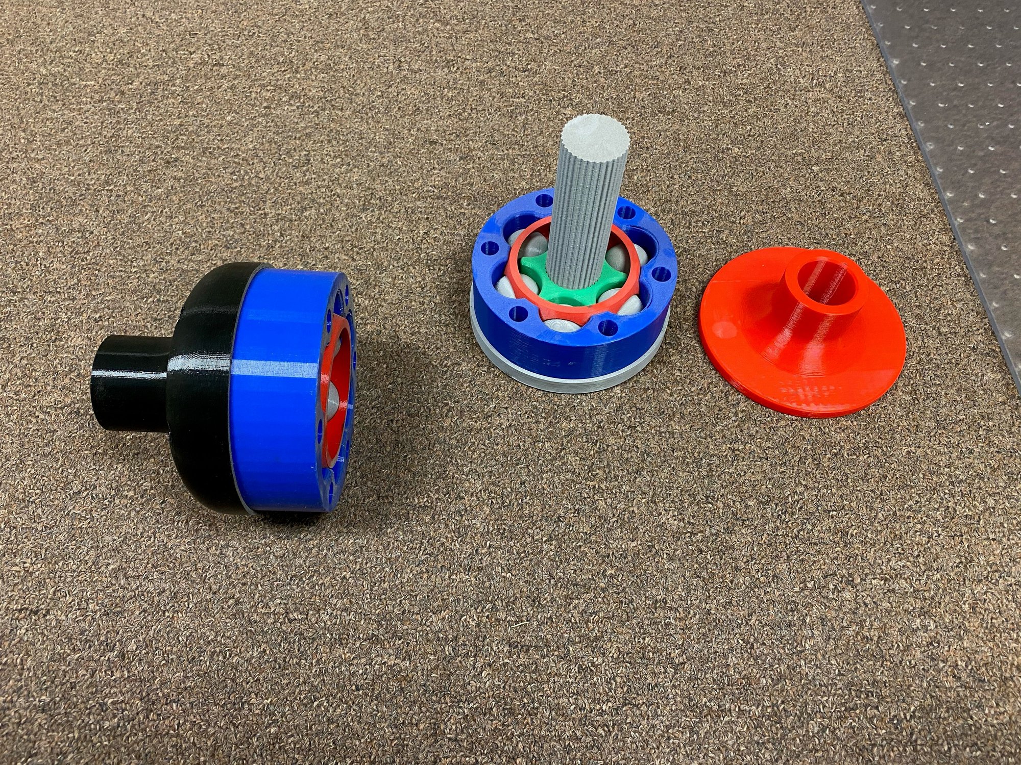
I don't like the slop in my DBL Carden (BW 72x w/ 1.5 ratio to 1:1 Arneson 1720 (ASD-6) direct drive) and have been looking into 934 CVs. My plan is basically custom machine a flange that bolts to the input of the drive (SAE 10-spline), machine an adapter with a rabbet fit to the existing BW flange and the 934, run a really short axle (full length splines probably) and use a giant heat shrink sleeve or boot of some type over the whole thing to keep the grease in. I went so far as to print the whole setup and test fit it, I even bolted it up and turned the trans/drive from the prop without any issue.
BUT I am only working with 450hp 454 Big blocks, I don't think they will survive ya'lls big diesels
.
BUT I am only working with 450hp 454 Big blocks, I don't think they will survive ya'lls big diesels
.
Last edited by sailtexas186548; 05-03-2021 at 05:37 PM. Reason: added picture
The following 6 users liked this post by sailtexas186548:
2187 (05-05-2021), bulletbob (05-04-2021), Gimme Fuel (05-04-2021), kidturbo (05-05-2021), ksalmine (05-04-2021), resurrected (05-04-2021)
05-03-2021, 05:38 PM
#1185
Where is the crankshaft centerline relation to the #6 cutout crankshaft centerline ?
do the wedge plates have to cover the cutout and relocate the drive up/down?
what does 2 degrees do to the propshaft height ( transom 15, assembly 13, ) ?
See me and angles again, thinking 13 degree transom ='s parrallel crank and prop, 2 degree wedge ='s same but lowers prop,
and 2 degrees over that 5 feet is alot. Or am i over thinking ?
edit in the 3 for the engines, 5 degrees over 5 feet ?
Last edited by outonsafari; 05-03-2021 at 05:45 PM. Reason: Forgot the 3 for the engines
05-03-2021, 05:41 PM
#1186
I don't like the slop in my DBL Carden (BW 72x w/ 1.5 ratio to 1:1 Arneson 1720 (ASD-6) direct drive) and have been looking into 934 CVs. My plan is basically custom machine a flange that bolts to the input of the drive (SAE 10-spline), machine an adapter with a rabbet fit to the existing BW flange and the 934, run a really short axle (full length splines probably) and use a giant heat shrink sleeve or boot of some type over the whole thing to keep the grease in. I went so far as to print the whole setup and test fit it, I even bolted it up and turned the trans/drive from the prop without any issue.
BUT I am only working with 450hp 454 Big blocks, I don't think they will survive ya'lls big diesels
.
BUT I am only working with 450hp 454 Big blocks, I don't think they will survive ya'lls big diesels
.
05-03-2021, 07:04 PM
#1187
Registered
Thread Starter
Where is the crankshaft centerline relation to the #6 cutout crankshaft centerline ?
do the wedge plates have to cover the cutout and relocate the drive up/down?
what does 2 degrees do to the propshaft height ( transom 15, assembly 13, ) ?
See me and angles again, thinking 13 degree transom ='s parrallel crank and prop, 2 degree wedge ='s same but lowers prop,
and 2 degrees over that 5 feet is alot. Or am i over thinking ?
edit in the 3 for the engines, 5 degrees over 5 feet ?
do the wedge plates have to cover the cutout and relocate the drive up/down?
what does 2 degrees do to the propshaft height ( transom 15, assembly 13, ) ?
See me and angles again, thinking 13 degree transom ='s parrallel crank and prop, 2 degree wedge ='s same but lowers prop,
and 2 degrees over that 5 feet is alot. Or am i over thinking ?
edit in the 3 for the engines, 5 degrees over 5 feet ?
Question-2, wedge plates basically just shim for the transom on the bottom, change angle but move nothing up or down.
Question-3, yes 2 deg over 5ft is equals a couple inches. However the transom angle really doesn't count for anything if making new boxes. All the powertrain angles are based off of the bottom of the boat. See old link in post above.
I don't have any really good pictures from original #6 setup that shows where prop shaft was set factory. However the #6 boxes we mocked up with, were not square like the others I've seen, and had some upward tilt angle built in. 2.5 deg overall I believe, will dig up the angle indicator pic. End result, they gained some angle but not near enough. A wedge plate on them might work, but still leaves the yoke flange a few inches low to gain back that 4 inches.
Have you think about CV joints? They have no angle speed error, or whatever it real name is in English, so you can run it not parallel.
I will use these in my Fountain. Transmash will make 6000lb/ft torque, of course split half when overdrive 1:1.8 and again split half to two drives but there is 1500lb/ft left torture CV joints and 934 Crmo joints should keep alive.
https://www.racereadyproducts.com/cv...934-cv-joints/
CV joints have axial play so you don't need spline slide in cardan.
I will use these in my Fountain. Transmash will make 6000lb/ft torque, of course split half when overdrive 1:1.8 and again split half to two drives but there is 1500lb/ft left torture CV joints and 934 Crmo joints should keep alive.
https://www.racereadyproducts.com/cv...934-cv-joints/
CV joints have axial play so you don't need spline slide in cardan.
Last edited by kidturbo; 05-03-2021 at 07:13 PM.
05-03-2021, 07:32 PM
#1188
Registered
Thread Starter
I don't like the slop in my DBL Carden (BW 72x w/ 1.5 ratio to 1:1 Arneson 1720 (ASD-6) direct drive) and have been looking into 934 CVs. My plan is basically custom machine a flange that bolts to the input of the drive (SAE 10-spline), machine an adapter with a rabbet fit to the existing BW flange and the 934, run a really short axle (full length splines probably) and use a giant heat shrink sleeve or boot of some type over the whole thing to keep the grease in. I went so far as to print the whole setup and test fit it, I even bolted it up and turned the trans/drive from the prop without any issue.
BUT I am only working with 450hp 454 Big blocks, I don't think they will survive ya'lls big diesels
BUT I am only working with 450hp 454 Big blocks, I don't think they will survive ya'lls big diesels
05-04-2021, 12:48 PM
#1190
Registered

