

40' Outlaw Upgrades - Twin 900Sc to 1000hp Duramax Diesels
 05-04-2021, 10:11 PM
#1191
Registered
Love the 3d work. Being how we twisted that 1480 slip yoke off when the gearset exploded, CV shaft gonna need scaled up to like 2" dia.. I've see a lot more half shafts twisted off in cranked up trucks than I have Spicer yokes. But it does solve most of these type issues pretty easily.
I may just reverse engineer the input shafts and have them cut for a better spline that yokes are available for but I�d rather not
 05-04-2021, 11:52 PM
#1192
Registered
Thread Starter
I knew that was driveshaft failure stated, but not that it was CV related. Result sounds totally reasonable. I've picked up a few blue pieces of metal from drivetrain and CP3 pump carnage already.
05-05-2021, 12:08 AM
#1193
Registered
Thread Starter
I think my drives input shafts were machined for a bolted on yoke like a differential pinion shaft, and a driveshaft with a slip joint, but I only have room for a DBL cardan that bolts to the 72c trans output and leave the yoke free to slide on the sae drive spline. The boat was originally rigged like this and it�s just not right...
Know where I could find a dfx or dwg of a #6 pattern? I can't even find the PDF with transom assembly dimensions now. Had all that saved at one time.
The following users liked this post:
2187 (05-05-2021)
The following users liked this post:
kidturbo (05-05-2021)
05-05-2021, 10:48 PM
#1195
i have to ask, if the boat was originally rigged with #6's, why did you not go with these from the start? driveline angles can be exaggerated if you were to, length permitting, increase the number of cross bearings on the driveline. i.e. each cross is good for 3 degrees of range so a typical drive line with two crosses = 6 degrees. increase the cross count and you increase the operating range of deflection. a center support bearing would be required for a shaft with greater than two crosses. fairly simple idea and execution. cv joints are good if the rpm are within the operating range of the cv. they are however costly in comparison to a cross bearing drive line.
05-06-2021, 10:23 AM
#1196
Registered
Thread Starter
The original 6's were plug-in style, with a 1.50 gear ratio. I was told they were dry sump, but after all I've learned, believe they were wet sumps. But either way, going with 2-spd transmissions would still have demanded moving things back for clearance. The ability to easily change up the gear ratio was a good selling point on the W's..
The following users liked this post:
2187 (05-09-2021)
05-14-2021, 02:29 AM
#1197
Registered
Thread Starter
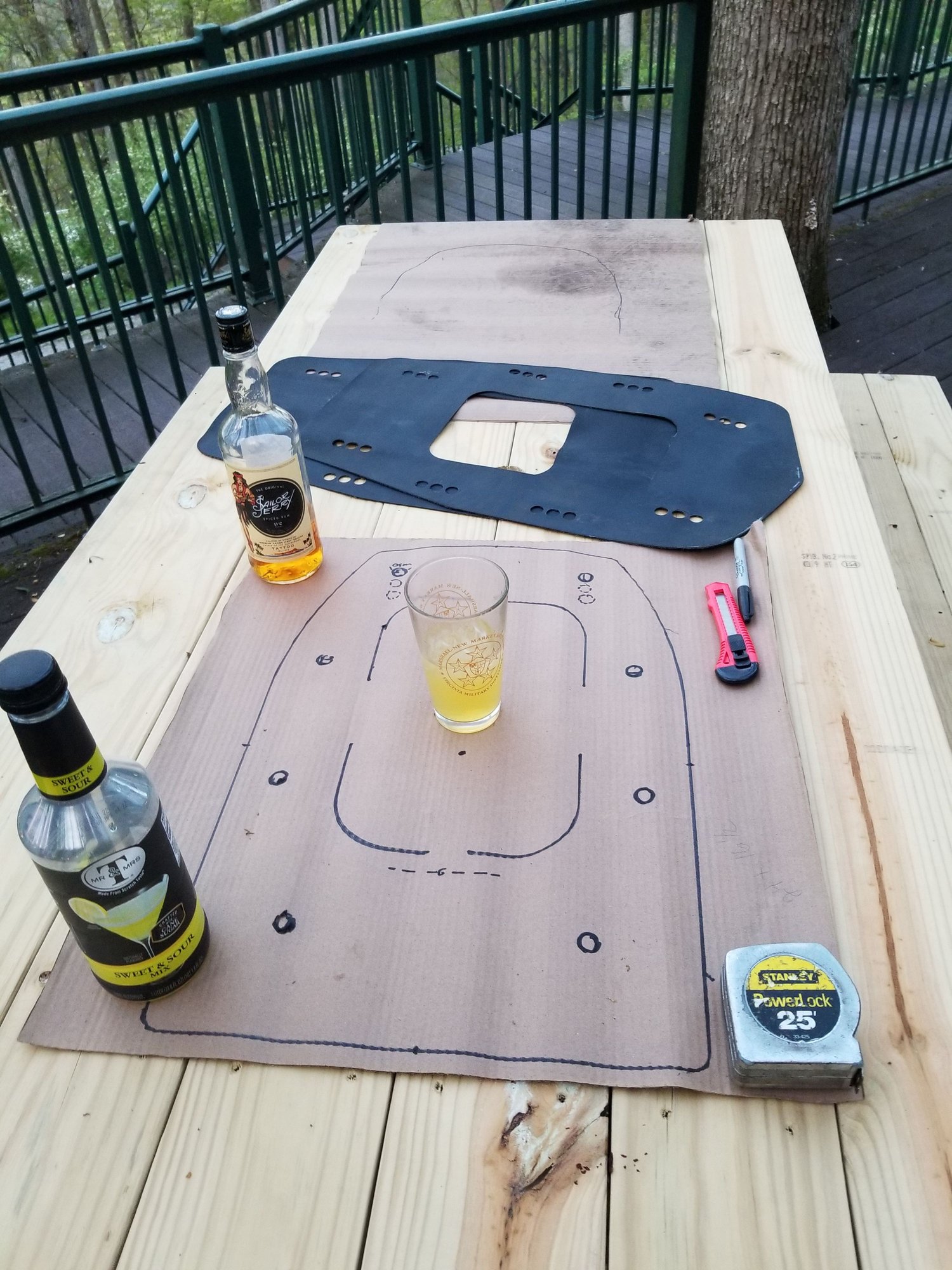
So I took a 3 day walk about into the mountains of WV along with my wife to relax and contemplate this new driveline setup. Got all serous, laid out the new cardboard templates on a picnic table, dug up all the pictures and measurements from our original designs, and stated working on the dimensions. But I needed something to hold down the templates.
I also brought along a fifth of 92 proof rum, then we picked up a half dozen bottles of wine, and some tasty tenderloin steaks. Things get a little fuzzy, I wake up in a hot tube, and this strange drawing is on my computer.. Have no idea what it means, but believe the answer I'm looking for is in there somewhere.. Please let me know if ya spot it.


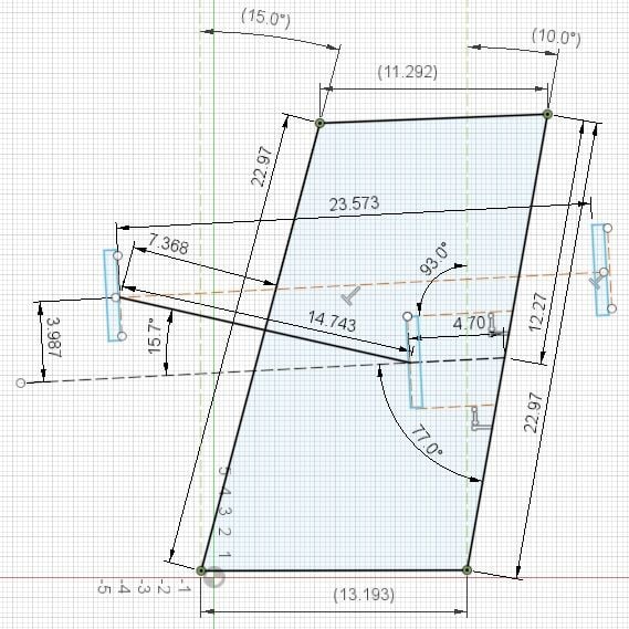
I also brought along a fifth of 92 proof rum, then we picked up a half dozen bottles of wine, and some tasty tenderloin steaks. Things get a little fuzzy, I wake up in a hot tube, and this strange drawing is on my computer.. Have no idea what it means, but believe the answer I'm looking for is in there somewhere.. Please let me know if ya spot it.
The following 2 users liked this post by kidturbo:
2187 (05-14-2021), Gimme Fuel (05-17-2021)
05-14-2021, 04:26 PM
#1198
your making a big intermediate standoff box that covers the stock 6 hole and raises the stock box, t-assy and drive.
somewhere in there maybe the factory box has 3 mounting locations any of which have acceptable drive line angles.
the whole set up will net the prop within an inch distance from transom and 1-2 inches in elevation.
That's my w.a.g. but would really like to some pics looking sqaure at the transom @ approx crank centerline.
smart money says you cyphered it all out.
The following users liked this post:
kidturbo (05-14-2021)
05-14-2021, 07:47 PM
#1199
Gold Member
This may be very old within the OSO community but I hadn’t seen it until recently.
When my small brain saw your diagram, I immediately thought of the Turbo Encabulator.
When my small brain saw your diagram, I immediately thought of the Turbo Encabulator.
The following 2 users liked this post by rak rua:
Gimme Fuel (05-17-2021), kidturbo (05-14-2021)
05-15-2021, 12:37 AM
#1200
Registered
Thread Starter
Your both right. There was a lot of alcohol involved in that drawing .. 
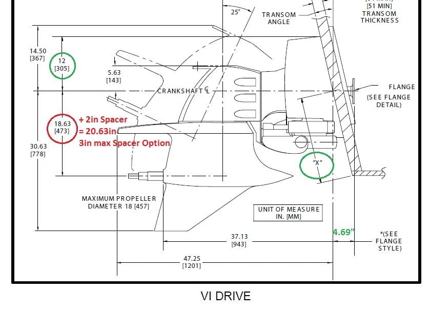
I've been trying to weigh the options before we start welding up aluminum plates. It's a tough call, and I'd forgot how much math went into the original design. What doesn't help is more that slight differences between the W's and 6 Mercs. The driveshaft carrier flanges on 6's are about 4 inches lower and 8 inches forward of the W's before you add boxes. As you can see in pics below. Not to mention change in height from the gimbal ring pivot / input-shaft centerline to prop-shaft centerline. The W's are a 15" drop, where the 6's are 18.6" before you add spaces..
So while our drive-shafts are getting much shorter, drive side flanges are also lower, and then we are limited to 3" max shim spacers on lower uints to recover what gets taken up in these new Jacked Up Boxes. We have to raise the 6's a minimum of 2",, and add 3deg of downward tilt, just to run a std driveshaft. Option B, was run a Double Cardan joint, which requires matching the [pinion] / drive side flange angle to the driveshaft. Which would jack all the lower angles out like 8-12deg in the opposite up direction. While common in 4x4's, not really desirable in boats.. Also see CV pic below..
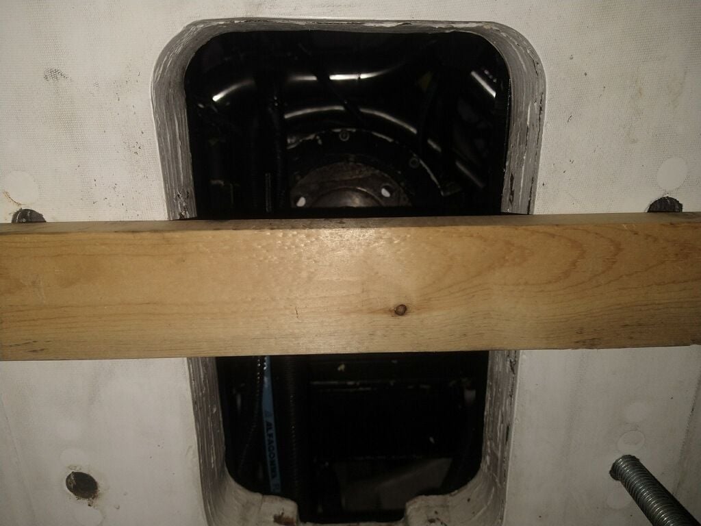
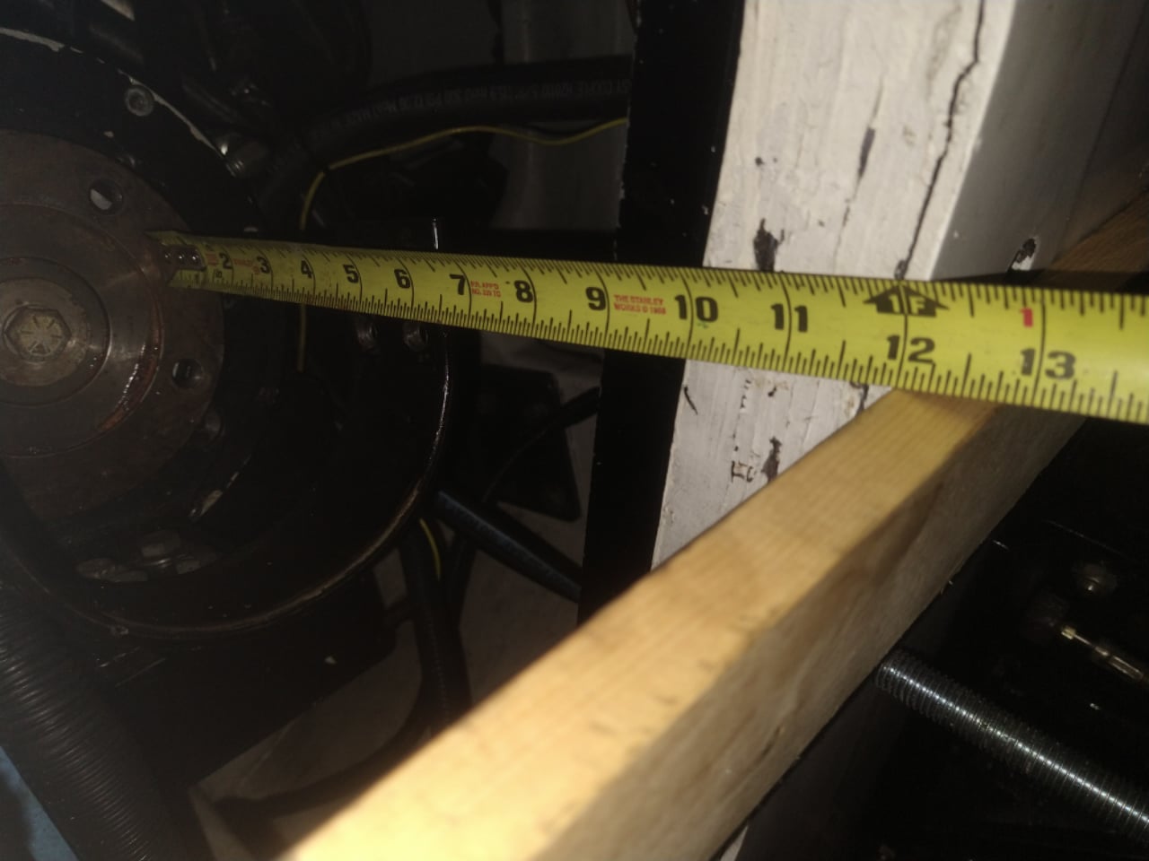
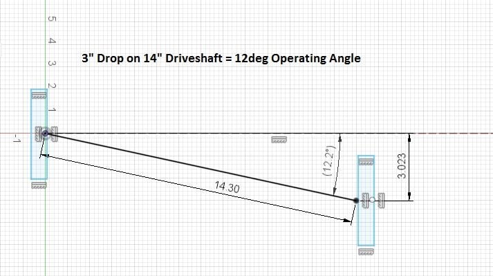
But we got a break today when received pics showing we actually have 12" between the transmission flange and the outside of transom. Adding 4.6" back to what I had calculated in the centerline drawing above. Every inch counts, and if using 12" extension boxes may just get our driveshaft angle in a happy condition. According to my driveshaft guru up here, a Spicer 1480 single cardan can safely operate up to about 12deg fully loaded. Preferably under 10deg, but not constrained to the 4deg I estimated above. Next to figure out how much down trim angle #6 lowers are capable of. If going this route, we'll be robbing 3deg of down trim in the extension box.. Plus our final prop height will land about where the W's are set now, even with those extra 2" shim plates in there..
Back to the Rum..
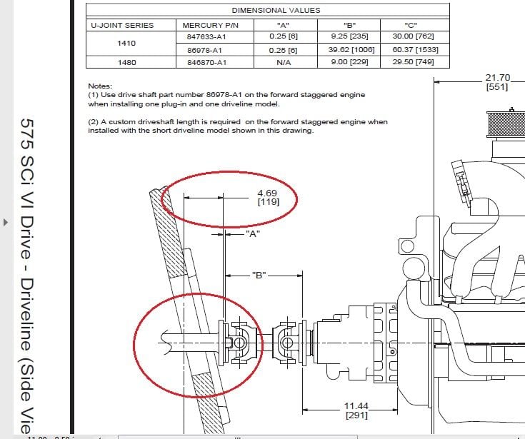
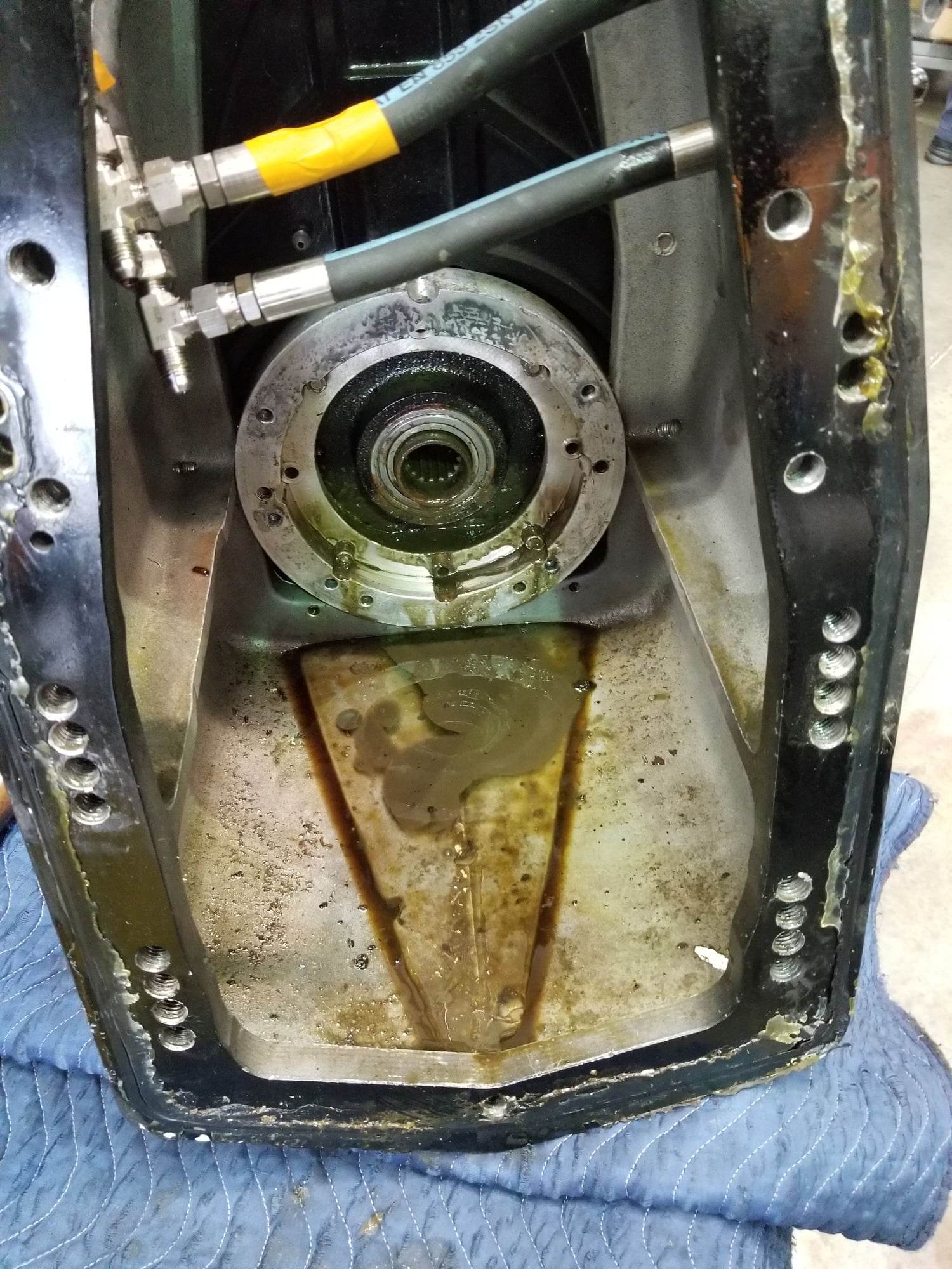
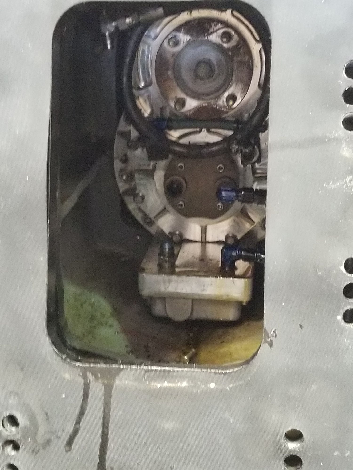
Why Double Cardan Doesn't Work.
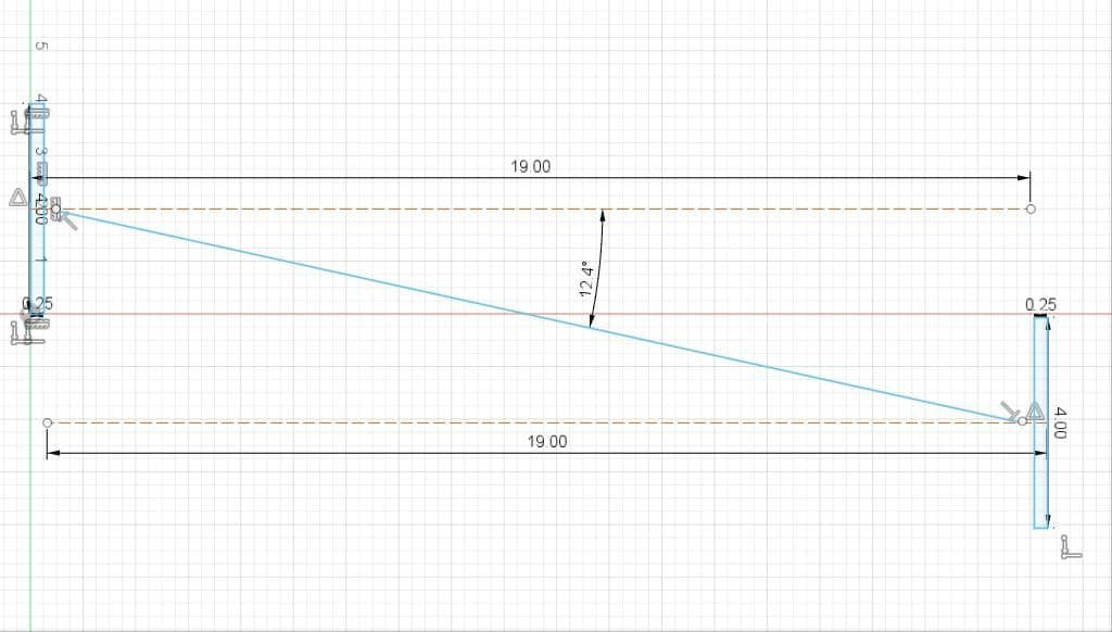
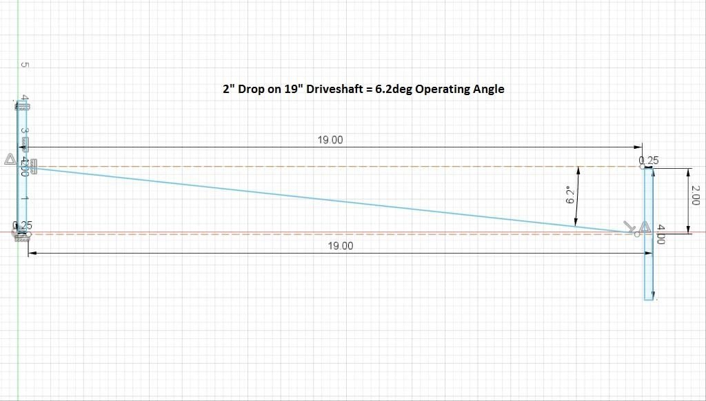
Where I hope to land..
I've been trying to weigh the options before we start welding up aluminum plates. It's a tough call, and I'd forgot how much math went into the original design. What doesn't help is more that slight differences between the W's and 6 Mercs. The driveshaft carrier flanges on 6's are about 4 inches lower and 8 inches forward of the W's before you add boxes. As you can see in pics below. Not to mention change in height from the gimbal ring pivot / input-shaft centerline to prop-shaft centerline. The W's are a 15" drop, where the 6's are 18.6" before you add spaces..
So while our drive-shafts are getting much shorter, drive side flanges are also lower, and then we are limited to 3" max shim spacers on lower uints to recover what gets taken up in these new Jacked Up Boxes. We have to raise the 6's a minimum of 2",, and add 3deg of downward tilt, just to run a std driveshaft. Option B, was run a Double Cardan joint, which requires matching the [pinion] / drive side flange angle to the driveshaft. Which would jack all the lower angles out like 8-12deg in the opposite up direction. While common in 4x4's, not really desirable in boats.. Also see CV pic below..
But we got a break today when received pics showing we actually have 12" between the transmission flange and the outside of transom. Adding 4.6" back to what I had calculated in the centerline drawing above. Every inch counts, and if using 12" extension boxes may just get our driveshaft angle in a happy condition. According to my driveshaft guru up here, a Spicer 1480 single cardan can safely operate up to about 12deg fully loaded. Preferably under 10deg, but not constrained to the 4deg I estimated above. Next to figure out how much down trim angle #6 lowers are capable of. If going this route, we'll be robbing 3deg of down trim in the extension box.. Plus our final prop height will land about where the W's are set now, even with those extra 2" shim plates in there..
Back to the Rum..
Why Double Cardan Doesn't Work.
Where I hope to land..

