

1979 Hallett Mini Day Cruiser Restoration
 11-19-2025 | 02:48 PM
#11
Thread Starter
Registered
Joined: Aug 2025
Posts: 33
Likes: 35
I drove over to Smeding Performance this morning to watch the engine be tuned on the dyno. They started with four pulls at 30deg advance, then three pulls at 32deg, then two pulls at 34deg. 34deg showed very little improvement over 32deg, and 32deg was only ~10-15 hp/tq above 30deg. We decided to keep the timing at 30deg and be a bit conservative. We ended up at 501hp/544tq with a very flat torque curve. Pretty happy overall!


 01-01-2026 | 07:24 PM
#12
Thread Starter
Registered
Joined: Aug 2025
Posts: 33
Likes: 35
Over the last few weeks, I installed the Bravo HP transom assembly, fabricated new engine mounts, drilled the six engine mount holes through the stringers and bonded in Garolite sleeves to ensure no water intrusion, and installed the engine. I rebuilt the stock Delco 10MT starter, but then realized the new engine has a 14" flywheel vs the stock 12.75" flywheel. I needed to keep the larger flywheel to accommodate the Bravo engine coupler, so the stock starter was not compatible. I ended up installing a Powermaster 9612 mini starter, which left a lot more room for the exhaust routing.
The stock alternator mount attached to the old exhaust manifolds, so we've had to get creative and fabricate some parts to make it work. I will be running a Hardin Gen 4 raw water pump.
The next step will be laying out and fabricating the exhaust.

The stock alternator mount attached to the old exhaust manifolds, so we've had to get creative and fabricate some parts to make it work. I will be running a Hardin Gen 4 raw water pump.
The next step will be laying out and fabricating the exhaust.

 01-08-2026 | 02:02 PM
#15
Thread Starter
Registered
Joined: Aug 2025
Posts: 33
Likes: 35
Tartilla
Yes! Its a 427cid SBC. Here are the major parts:
Yes! Its a 427cid SBC. Here are the major parts:
- Dart SHP block, 1-piece rear main seal
- Smeding 4340 Forged Steel Crankshaft, Internal Balance, 4.000" Stroke
- Smeding 4340 Forged Steel H-Beam Rods with 7/16" Bolts, 6.000" Length
- Icon IC850KTD.STD Pistons w/Marine Ring Gaps (9.72:1 static compression ratio)
- Smeding 210CC aluminum heads (65cc chambers, 2.08"/1.60" valves)
- AFR Inconel exhaust valves
- ARP head bolts
- Cometics MLS head gasket (custom thickness to get .040" quench)
- Jones Cams custom hydraulic roller cam (.232/.236 @ .050", .540/.540 lift with 1.5:1 rockers, 114 LSA, 1.130" base circle). This cam has 6deg of overlap, which Mike said is completely safe from wet exhaust reversion.
- Gatorman link-bar hydraulic roller lifters
- Smeding 1.5:1 ratio, 3/8" stud, full-roller rocker arms
- Edelbrock RPM Air-Gap Intake Manifold
- Edelbrock 1410 750CFM marine carburetor
- Melling oil pump
- Smeding valve covers
- Davis Unified Ignition Marine Performance HEI distributor
- Summit SFI rated balancer
- Moroso 20206 7qt oil pan
- Holley 80GPH fuel pump
- 14" 168 tooth billet flywheel
Last edited by OGHallett; 01-08-2026 at 09:06 PM.
01-24-2026 | 06:37 PM
#16
Thread Starter
Registered
Joined: Aug 2025
Posts: 33
Likes: 35
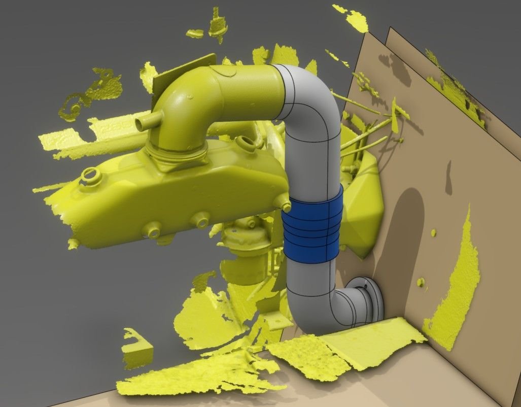
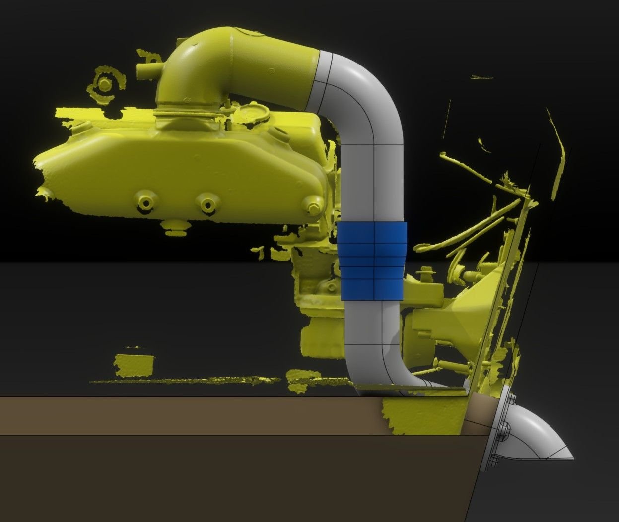
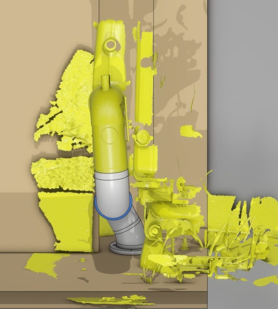
found a set of Stainless Marine risers for $600 that are in great shape (usually around $1600 new). I used a consumer grade 3D scanner to scan the left side riser, manifold, engine, and transom assembly so I could design the exhaust. These risers introduce the cooling water into the exhaust gas fairly close to the manifold, so I plan to have a fabricator extend both the inner and outer tubes of the riser so the cooling water is introduced part way down the side of the motor. My hope is that this will reduce any chance of reversion. I will have a 4" to 3.5" silicone coupler where the flows are mixed, then 3.5" tube out through the transom. The custom fitting at the transom will exit just below the waterline so the boat is quiet(er) when off-plane. They are shaped so that water will not be pushed up the exhaust when reversing or when water surges up against the transom (e.g. when coming off-plane). My hope is that when the boat is on plane, the noise of the exhaust will be partially absorbed by the water and will be a LITTLE more quiet than if it exits directly out the back.
So question for the experienced guys here...would you have any concerns with what I have designed here? Anything I am not thinking about?

So question for the experienced guys here...would you have any concerns with what I have designed here? Anything I am not thinking about?
Last edited by OGHallett; 01-26-2026 at 03:34 PM.
03-16-2026 | 10:49 AM
#17
Thread Starter
Registered
Joined: Aug 2025
Posts: 33
Likes: 35
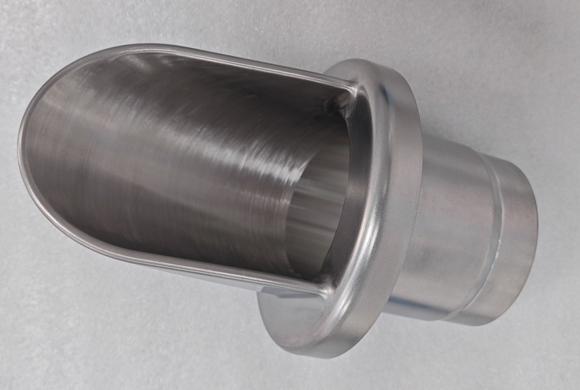
It's been a while waiting on the machined exhaust components, but they are finally completed. Welding should happen early next week, and I'm hoping to have the exhaust installed in the next 3 weeks.
These are machined from 316 Stainless. I intend to polish them before installing them on the boat.

These are machined from 316 Stainless. I intend to polish them before installing them on the boat.
03-17-2026 | 11:47 AM
#18
Platinum Member

Joined: May 2013
Posts: 1,442
Likes: 484
From: Huntington Beach
I would put some kind of an air brake in the system. With the exhaust underwater it will choke out the motor without any air in the system. A small 1-inch tube in the exhaust with a hose to air would do the trick.
03-17-2026 | 01:01 PM
#19
Thread Starter
Registered
Joined: Aug 2025
Posts: 33
Likes: 35
Thanks for the suggestion! The exhaust tip location is ~4.5" below the oval exhaust port in the transom assembly, and ~2.7" below the idle bypass ports in the transom assembly (both of these are blocked off). On this boat, the oval port typically sits at the waterline. That ~4.5" submersion (which I want for noise reduction at idle) would equate to less than 0.2psi of back pressure, so I am hoping that will not be an issue. Fingers crossed...


