

2006 Donzi 35 zfc renewal (CoPart special)
 11-12-2025 | 11:45 PM
#1
Thread Starter
Registered
Joined: Jun 2025
Posts: 16
Likes: 7
From: Shelton, CT
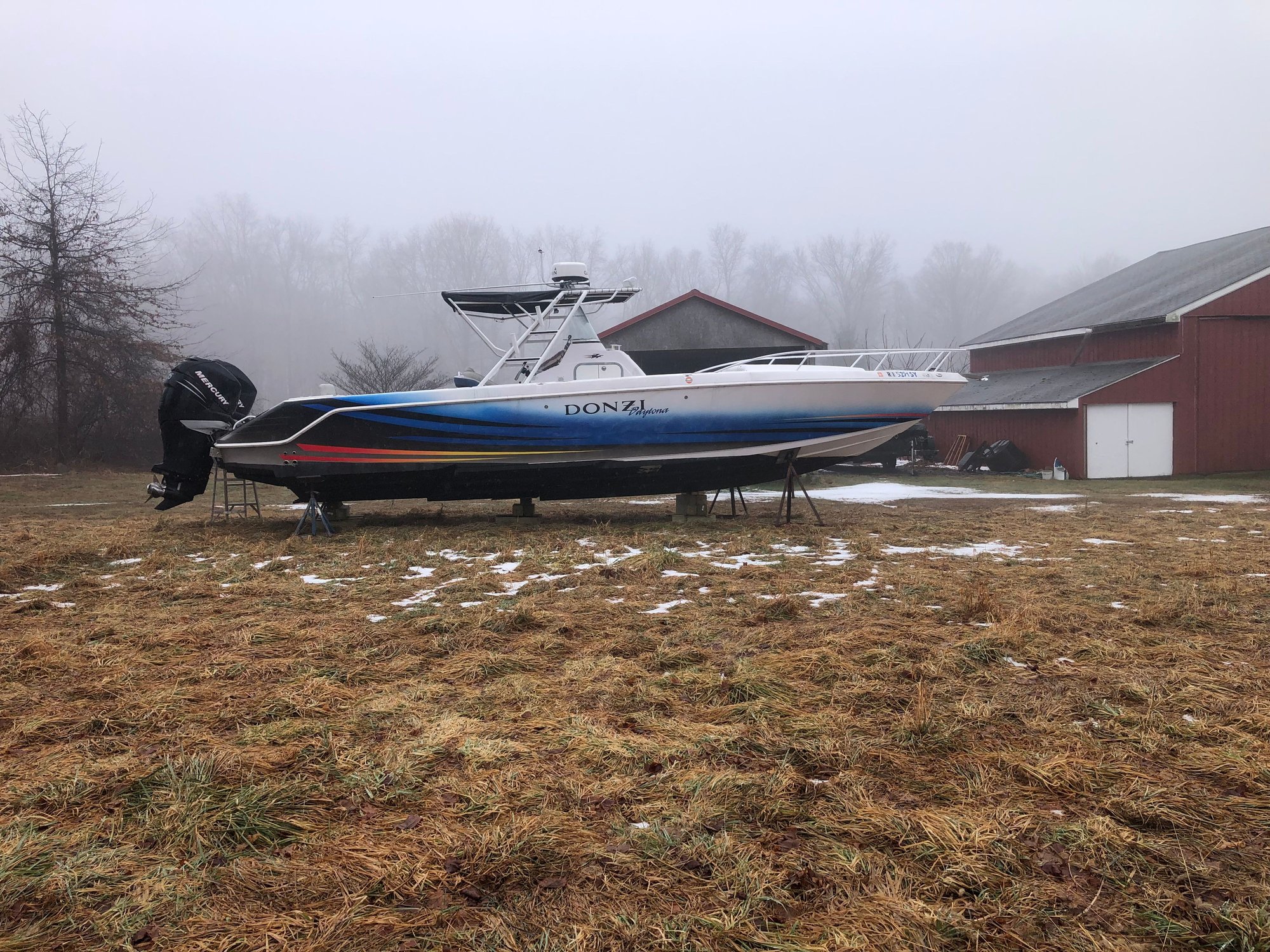
Here are some pictures and info on the progress of my Donzi/CoPart special. The boat was purchased at auction, it was a water/flood boat out of RI. First thing was to media blast the AF paint off the bottom followed by my plan to convert to triples. Boat came with twin 275 Verados which I managed to turn over by hand on the flywheel. So not frozen, filled cylinders with penetrating oil for some future rebuild.
Next was to reinforce transom, there were some splash well corner stress cracks so they would be addressed when the brackets were done. SS 316
tubed brackets were made connecting the transom to the stringer knee wall with additional SS brackets in the bilge area. I did not like the idea of connecting the brackets to the cap only.
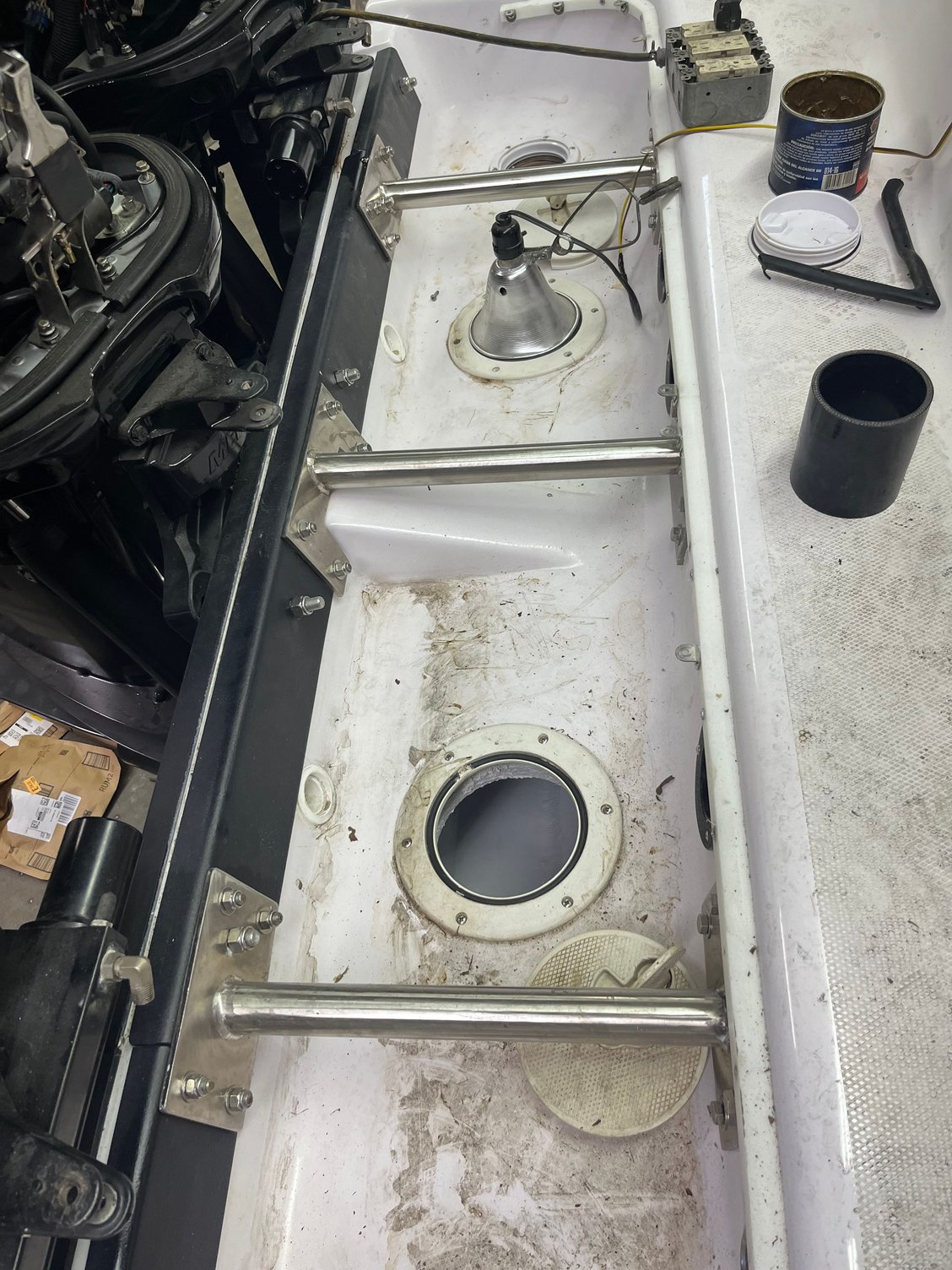
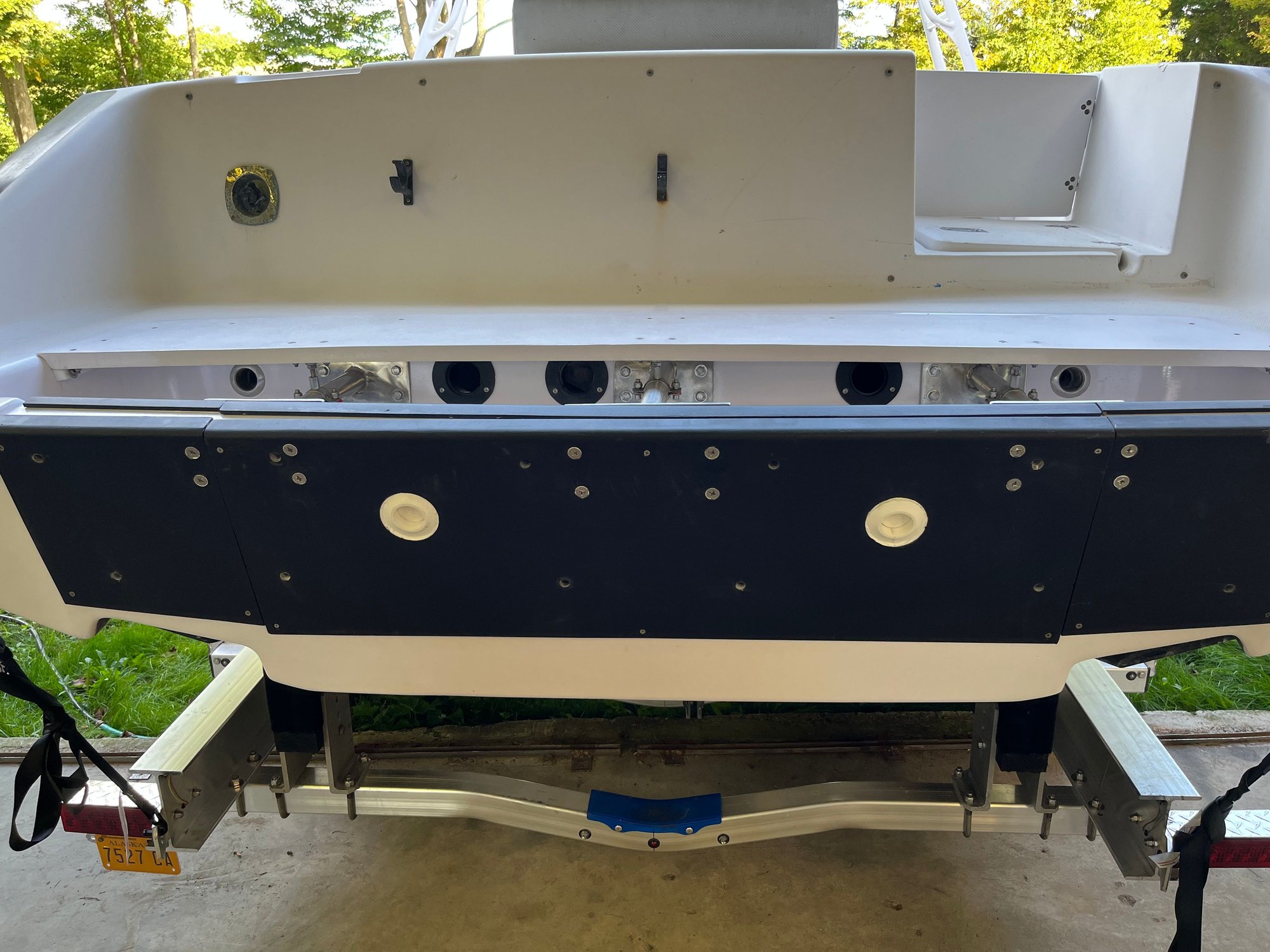
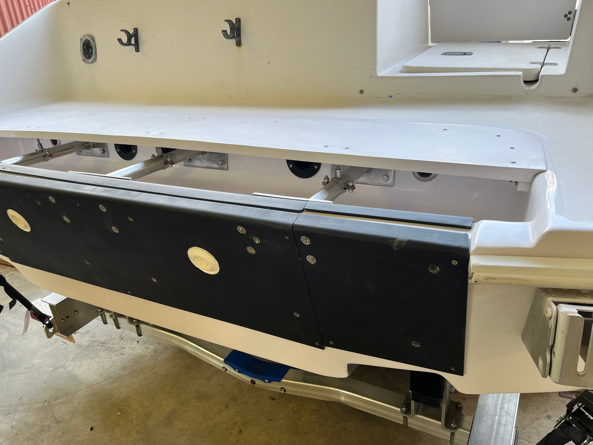
scuppers were moved and additional aluminum transom plates installed. At this time I made a panel to increase the width of the ledge forward of the splash well from 9� to 18-1/2� to provide a position to fish over the motors. Not my idea, the person who owned �Fantasea� added it on a motor retrofit.
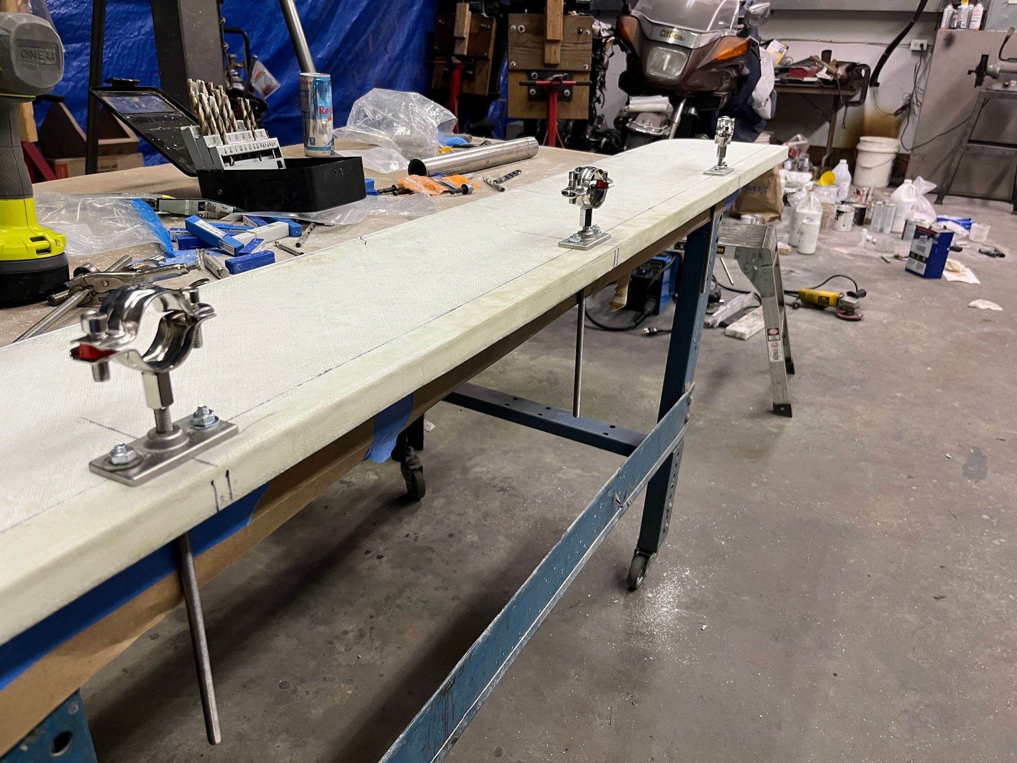
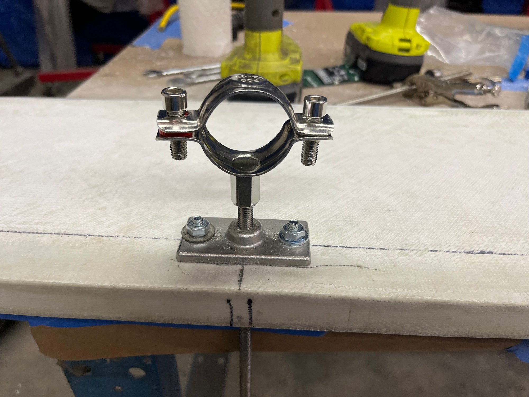
Found some metric SS pipe hangars that sit on the tubes to support the aft splash well panel. The forward panel and sides sit on a 3/4 x 1-0 inch thermoformed piece of PE.
The panel was made using 1� Nidacore with multiple layers of 1708 and hard points added where necessary to remove compression loads of fasteners. Gelcoated to match.
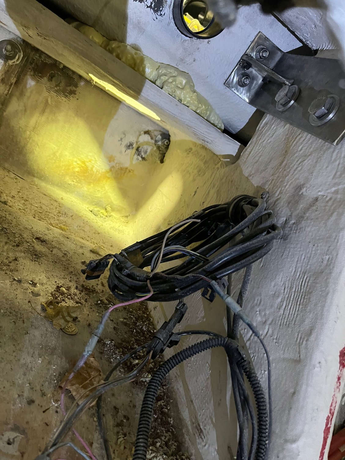
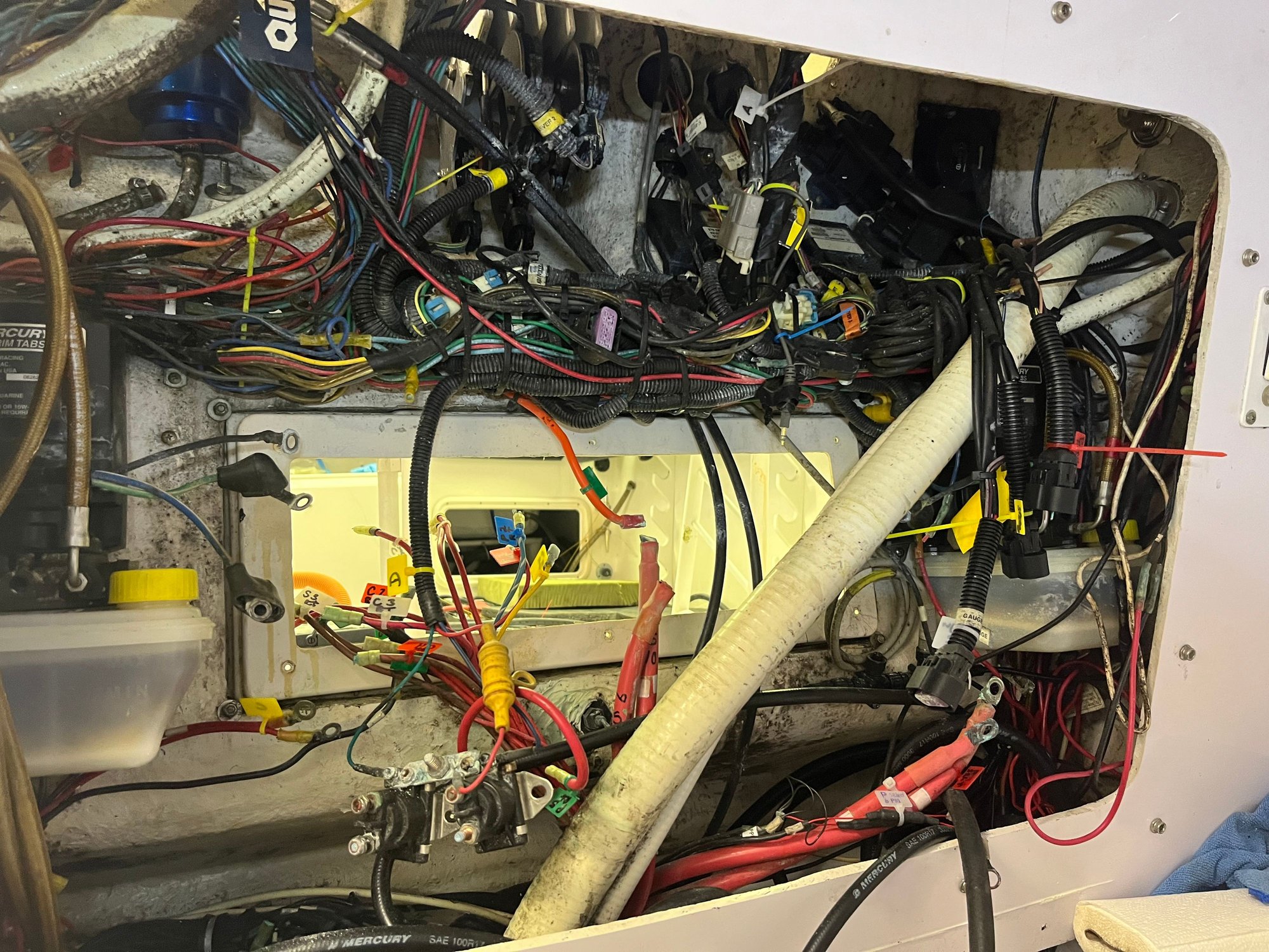
Bilge area is being
stripped out, cleaned and painted. SS gusseted brackets through bolted in stringer knee wall.
.
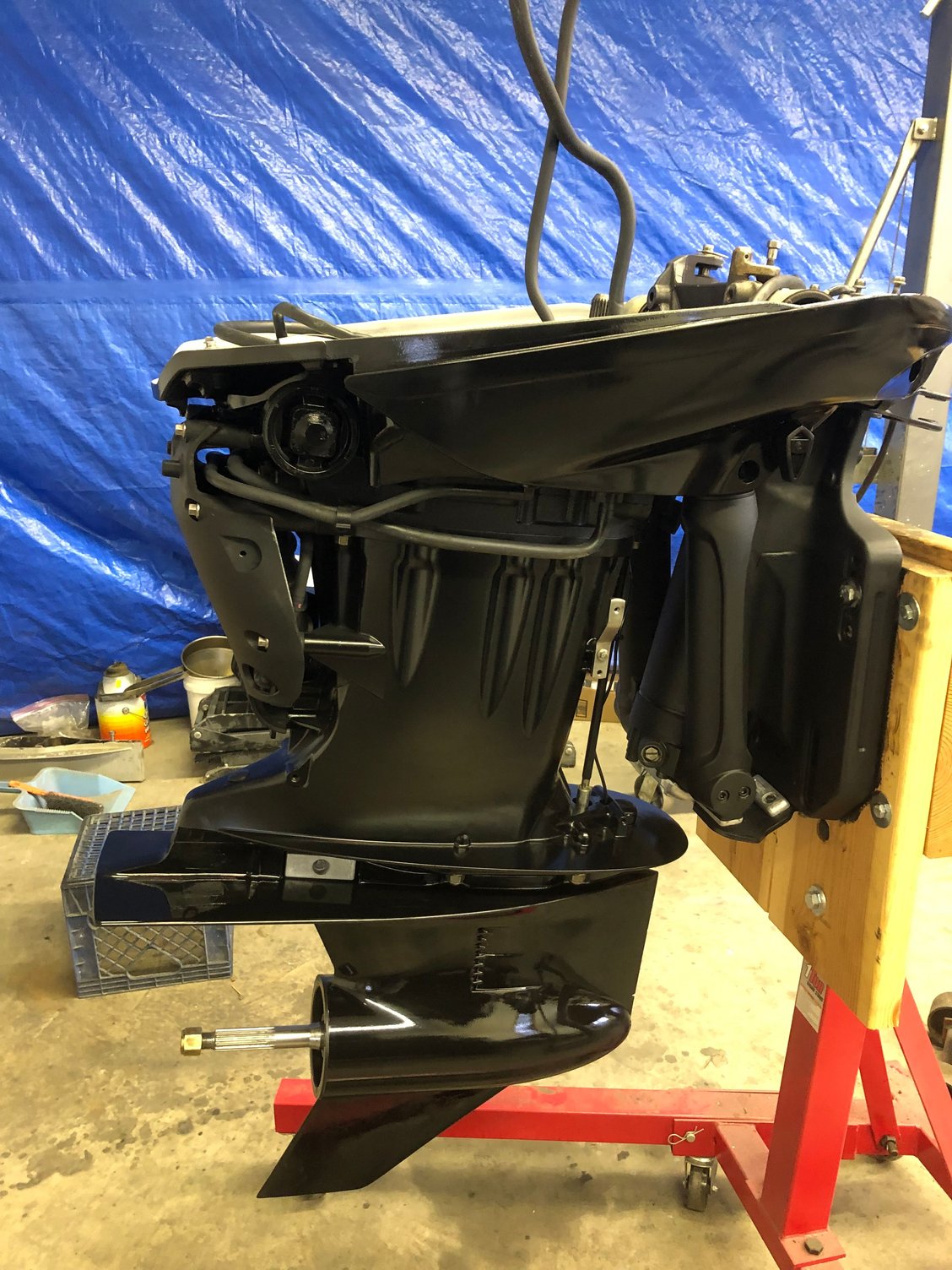
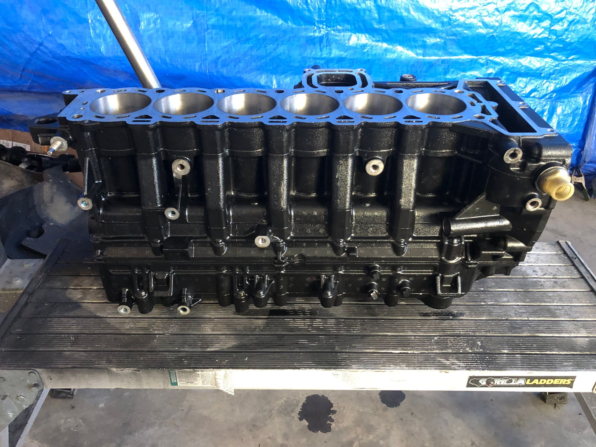
The motors are 2011 300 Vrods completely rebuilt, .020 over Wiseco forged pistons flashed 345 hp. Original 275�s were 25� shafts. Trips have 20� P/S 30� center. I�ve had the trip 300�s for about three years waiting for a hull. Nothing wrong with
them, just tired. They were (2) 25� shafts and 1 30� shaft. I bought the necessary parts to change the 25�s to 20�s and did the conversion. Rebuilt the P/S 5.44 lower units.
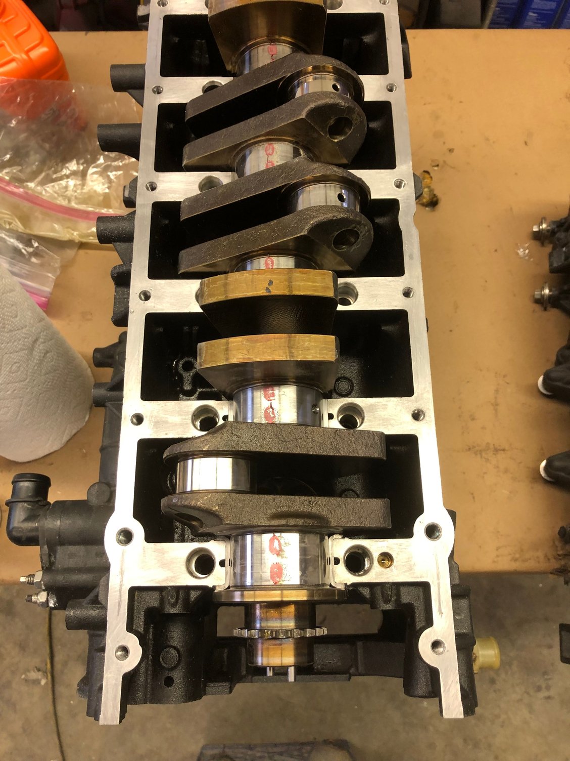
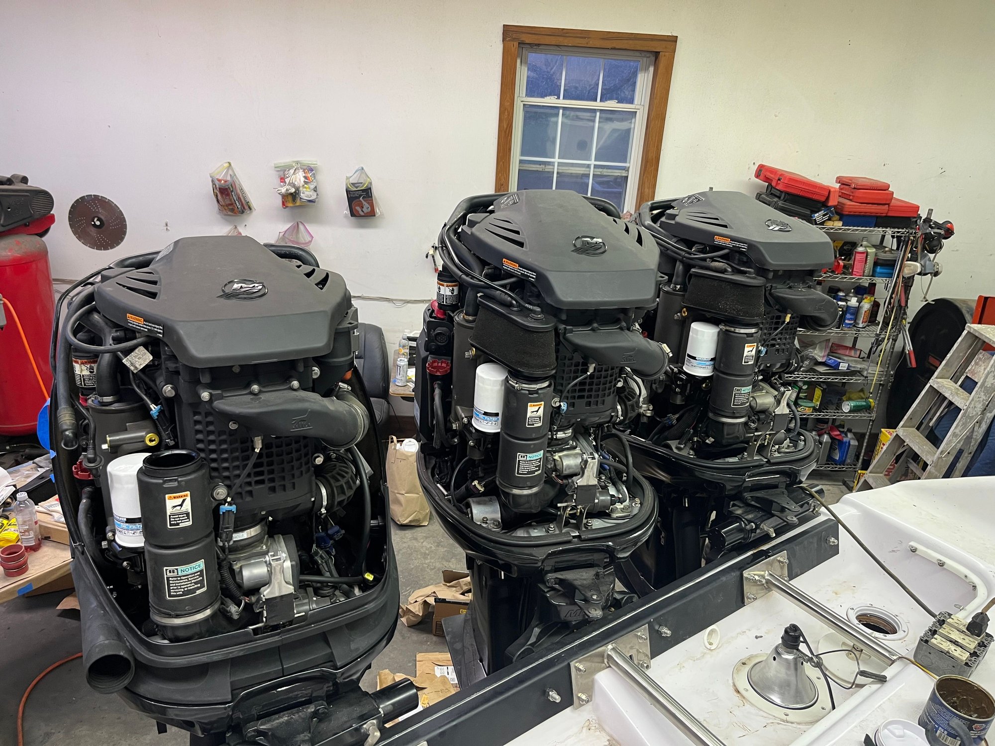
Getting ready for powerhead
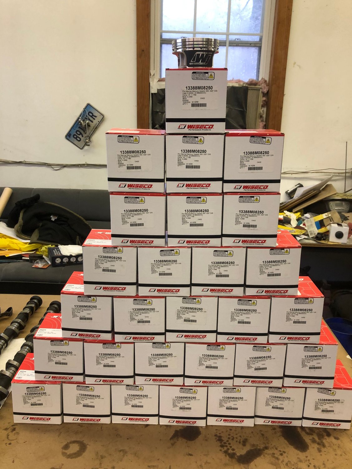
That�s a lot of pistons! Price break at 24, might as We�ll get 30 for the two motors I pulled off.
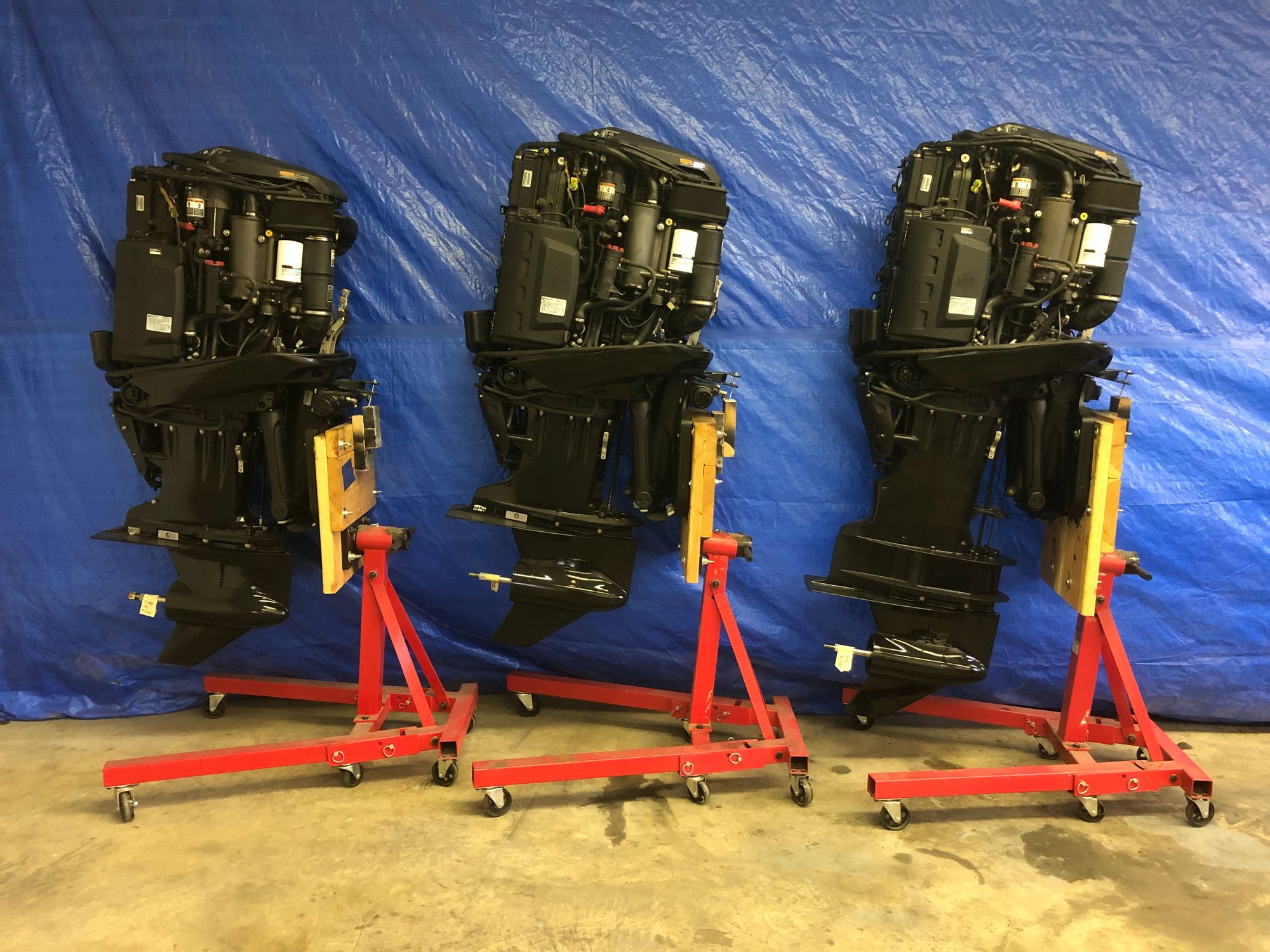
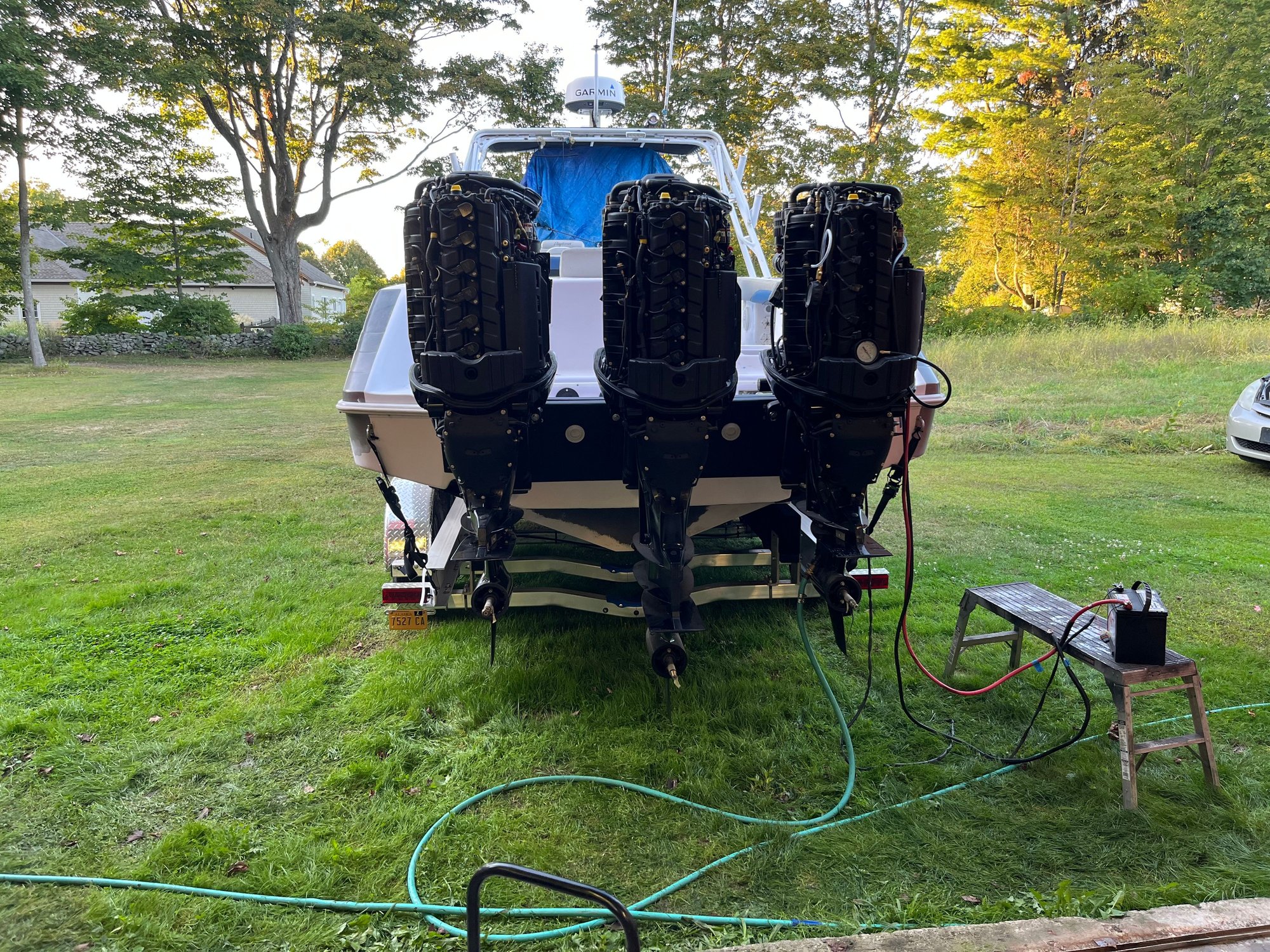
All done waiting to hang.
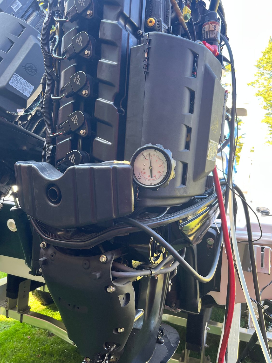
55 psi oil pressure, cold, idle.
First startup, idle, no rigging jumped ignition/fuel out.
Let the fun begin!
[img alt="Little bites grasshopper, little bites.
"]https://cimg4.ibsrv.net/gimg/www.offshoreonly.com-vbulletin/2000x1504/img_6540_a73900985d59ddce7e9c05a113aa1586bdda7010. jpeg[/img]
Little bites grasshopper, little bites.
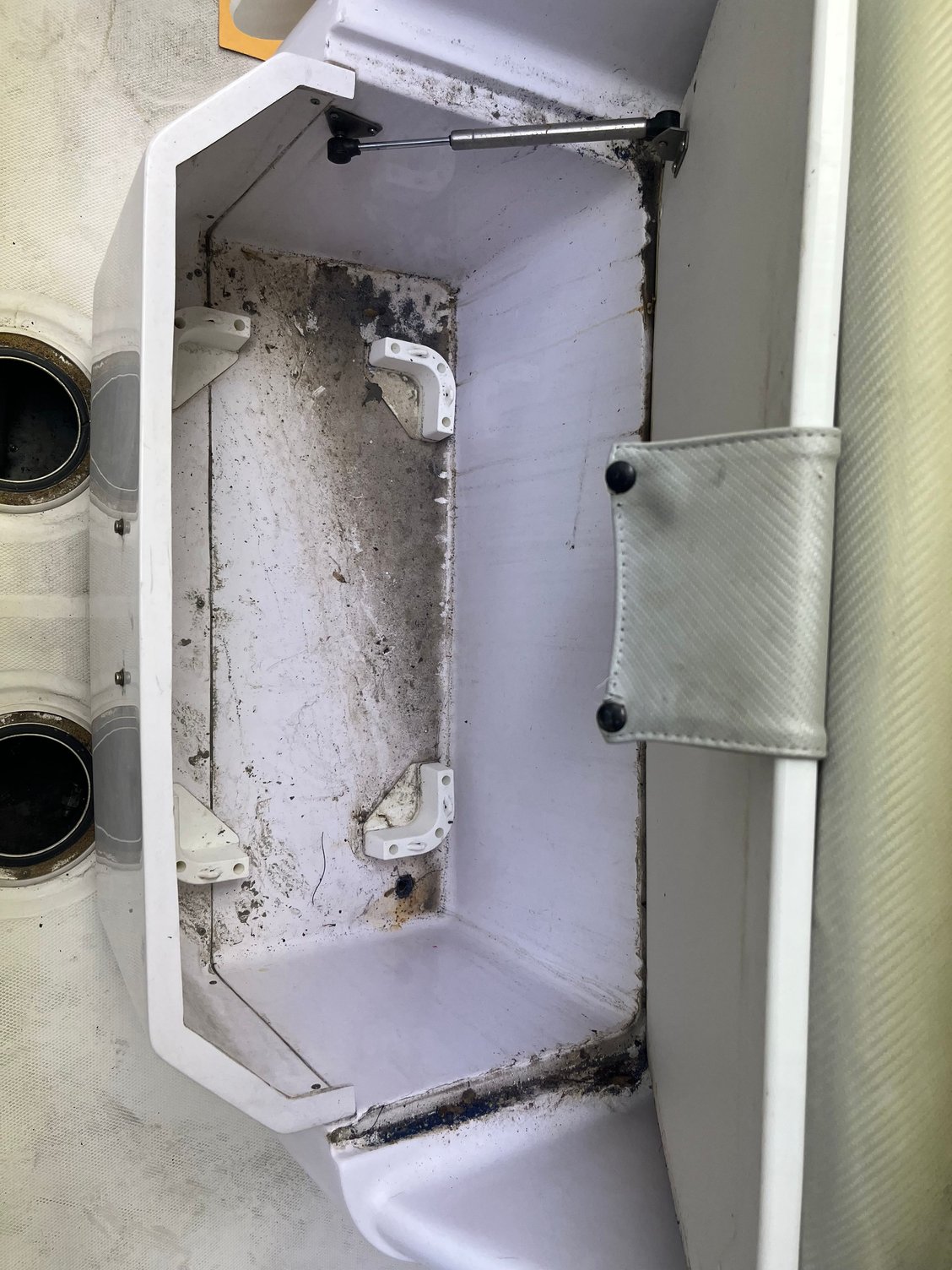
The boat came with a 186 gallon main tank and a 75 gallon forward aux tank for 261 gallons. That ain�t going to cut it. I had to keep the head/toilet, wife�s orders, so that space is out. Next was the step down area in the cuddy v berth area. That would be worth 35 gallons by my measurements.
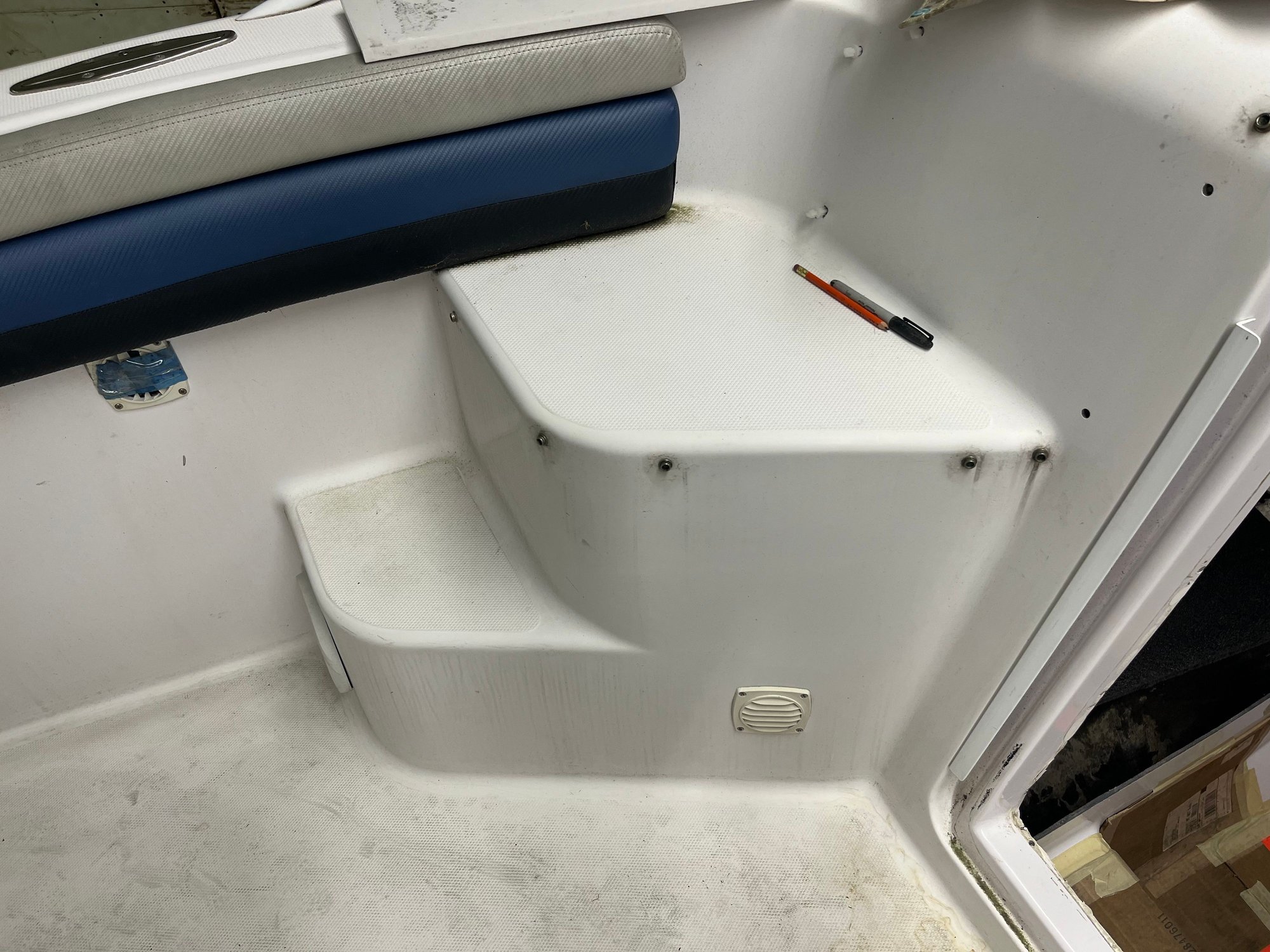
The only problem is now you�re crawling in on hands and knees, like a pup tent, no thanks too old.
Winner winner chicken 🐔 dinner. That�s worth 31 gallons. Cooler forward of console, and I get to keep seat.
still not enough.
What�s behind door number one?
Pulled out the trim and got out that new bi-metal sawzall blade that�s been sitting around and the dremel with a cut off wheel.
Port side, now I�m getting happy
Door number two
[img alt="Much happier
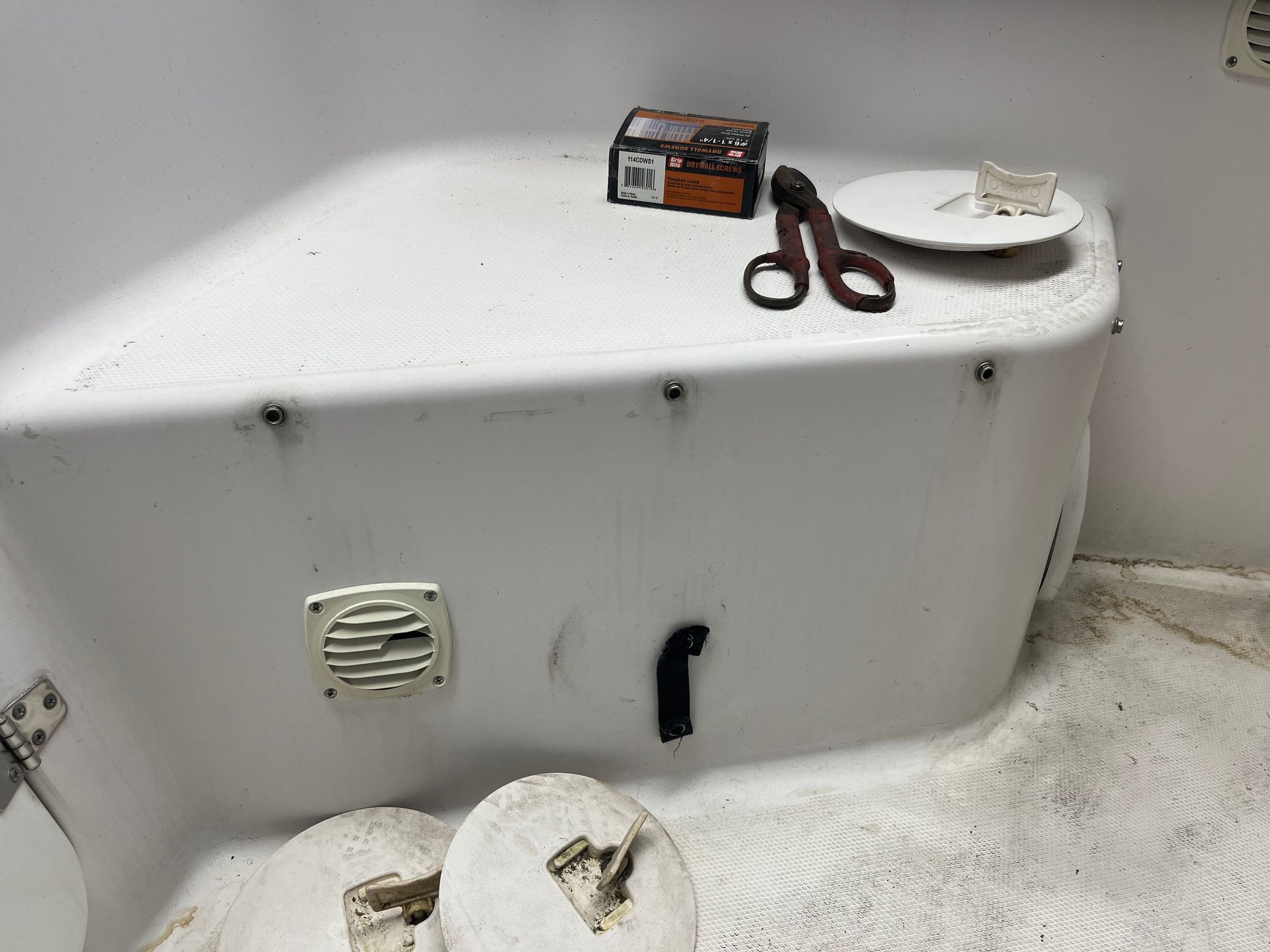
I calculate between 119-125 additional, useable gallons for a total of 380-385 gallons. Good for the long offshore runs. Fill them when you need them. Tanks will be constructed in place using the cavities as molds, with the exception of the �cooler� tank. One side will be left open and be finished off the boat. Contested will be used to fabricate the tanks, baffled and sealed prior to closing out the tanks. Aluminum plate will be bonded in where fitting penetrations are needed. "]https://cimg8.ibsrv.net/gimg/www.offshoreonly.com-vbulletin/2000x1504/img_6548_1c87e9e72600c77cc482799416a1bb2d6348ec87. jpeg[/img]
Much happier I calculate between 119-125 additional, useable gallons for a total of 380-385 gallons. Good for the long offshore runs. Fill them when you need them. Tanks will be constructed in place using the cavities as molds, with the exception of the �cooler� tank. One side will be left open and be finished off the boat. Vinyl ester will be used to fabricate the tanks, baffled and sealed prior to closing out the tanks. Aluminum plate will be bonded in where fitting penetrations are needed.
Tanks will conform to USCG regs. All fittings top of tank etc. The sending unit for the 2 step tanks at first was a bit problematic until I came across
Holley�s easy level sending unit. It uses lidar to determine fuel amount. Programmable for any size tank up to 36� deep, I think. The only thing about the sending units is they output a PWM signal and not resistance. I found a company that will supply me with a 3 channel encoding module, at a reasonable price that will convert the PWM to NMEA 2K so the farming will be happy. The
existing 75 gallon aux tank transfers fuel to the main tank through a 72 gph Carter 12V electric pump. I plan on manifolding the three new tanks to a second Carter pump with a separate line to the main tank. Each line at the manifold will have a cockpit controlled electric on/off valve with panel indicator. A turbine flow meter will be installed in the fuel line to indicate positive output of pumps. My thinking is that the pump could indicate on but how can you be assured fuel is being delivered? I will install some crossfeed valves in case one of them ****s the bed when you�re way out. Sorry for the posting screwup. To tired to fix.
That�s it for now
Pat
Next was to reinforce transom, there were some splash well corner stress cracks so they would be addressed when the brackets were done. SS 316
tubed brackets were made connecting the transom to the stringer knee wall with additional SS brackets in the bilge area. I did not like the idea of connecting the brackets to the cap only.
scuppers were moved and additional aluminum transom plates installed. At this time I made a panel to increase the width of the ledge forward of the splash well from 9� to 18-1/2� to provide a position to fish over the motors. Not my idea, the person who owned �Fantasea� added it on a motor retrofit.
Found some metric SS pipe hangars that sit on the tubes to support the aft splash well panel. The forward panel and sides sit on a 3/4 x 1-0 inch thermoformed piece of PE.
The panel was made using 1� Nidacore with multiple layers of 1708 and hard points added where necessary to remove compression loads of fasteners. Gelcoated to match.
Bilge area is being
stripped out, cleaned and painted. SS gusseted brackets through bolted in stringer knee wall.
.
The motors are 2011 300 Vrods completely rebuilt, .020 over Wiseco forged pistons flashed 345 hp. Original 275�s were 25� shafts. Trips have 20� P/S 30� center. I�ve had the trip 300�s for about three years waiting for a hull. Nothing wrong with
them, just tired. They were (2) 25� shafts and 1 30� shaft. I bought the necessary parts to change the 25�s to 20�s and did the conversion. Rebuilt the P/S 5.44 lower units.
Getting ready for powerhead
That�s a lot of pistons! Price break at 24, might as We�ll get 30 for the two motors I pulled off.
All done waiting to hang.
55 psi oil pressure, cold, idle.
First startup, idle, no rigging jumped ignition/fuel out.
Let the fun begin!
[img alt="Little bites grasshopper, little bites.
"]https://cimg4.ibsrv.net/gimg/www.offshoreonly.com-vbulletin/2000x1504/img_6540_a73900985d59ddce7e9c05a113aa1586bdda7010. jpeg[/img]
Little bites grasshopper, little bites.
The boat came with a 186 gallon main tank and a 75 gallon forward aux tank for 261 gallons. That ain�t going to cut it. I had to keep the head/toilet, wife�s orders, so that space is out. Next was the step down area in the cuddy v berth area. That would be worth 35 gallons by my measurements.
The only problem is now you�re crawling in on hands and knees, like a pup tent, no thanks too old.
Winner winner chicken 🐔 dinner. That�s worth 31 gallons. Cooler forward of console, and I get to keep seat.
still not enough.
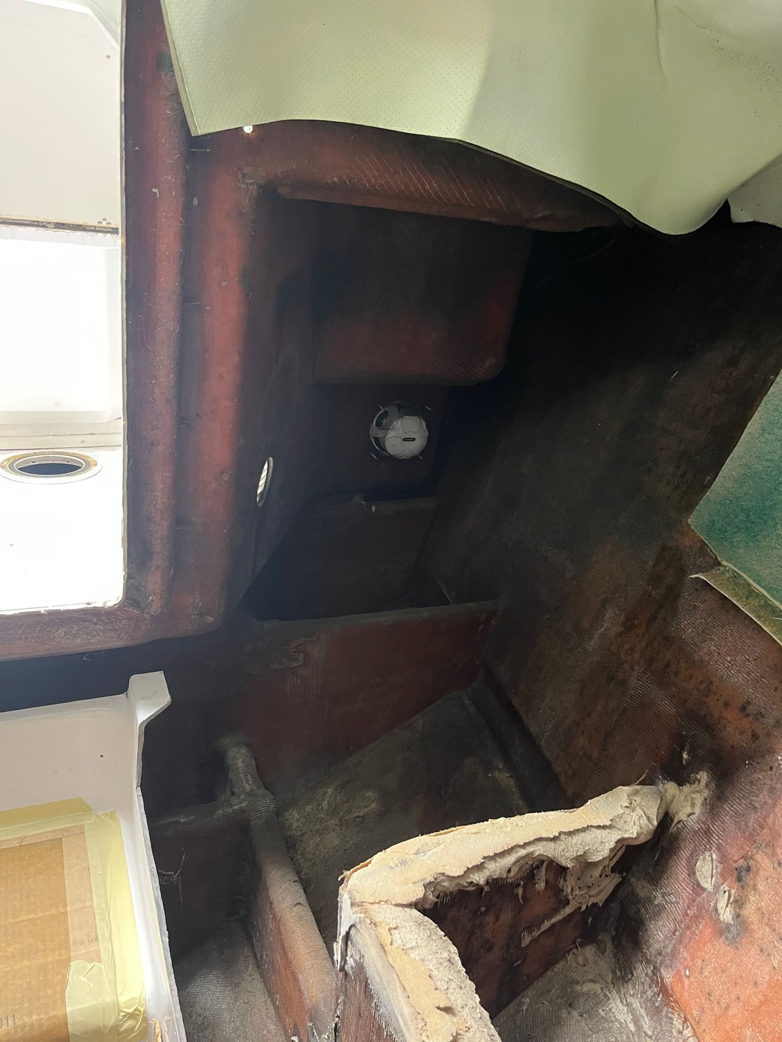
What�s behind door number one?
Pulled out the trim and got out that new bi-metal sawzall blade that�s been sitting around and the dremel with a cut off wheel.
Port side, now I�m getting happy
Door number two
[img alt="Much happier
I calculate between 119-125 additional, useable gallons for a total of 380-385 gallons. Good for the long offshore runs. Fill them when you need them. Tanks will be constructed in place using the cavities as molds, with the exception of the �cooler� tank. One side will be left open and be finished off the boat. Contested will be used to fabricate the tanks, baffled and sealed prior to closing out the tanks. Aluminum plate will be bonded in where fitting penetrations are needed. "]https://cimg8.ibsrv.net/gimg/www.offshoreonly.com-vbulletin/2000x1504/img_6548_1c87e9e72600c77cc482799416a1bb2d6348ec87. jpeg[/img]
Much happier I calculate between 119-125 additional, useable gallons for a total of 380-385 gallons. Good for the long offshore runs. Fill them when you need them. Tanks will be constructed in place using the cavities as molds, with the exception of the �cooler� tank. One side will be left open and be finished off the boat. Vinyl ester will be used to fabricate the tanks, baffled and sealed prior to closing out the tanks. Aluminum plate will be bonded in where fitting penetrations are needed.
Tanks will conform to USCG regs. All fittings top of tank etc. The sending unit for the 2 step tanks at first was a bit problematic until I came across
Holley�s easy level sending unit. It uses lidar to determine fuel amount. Programmable for any size tank up to 36� deep, I think. The only thing about the sending units is they output a PWM signal and not resistance. I found a company that will supply me with a 3 channel encoding module, at a reasonable price that will convert the PWM to NMEA 2K so the farming will be happy. The
existing 75 gallon aux tank transfers fuel to the main tank through a 72 gph Carter 12V electric pump. I plan on manifolding the three new tanks to a second Carter pump with a separate line to the main tank. Each line at the manifold will have a cockpit controlled electric on/off valve with panel indicator. A turbine flow meter will be installed in the fuel line to indicate positive output of pumps. My thinking is that the pump could indicate on but how can you be assured fuel is being delivered? I will install some crossfeed valves in case one of them ****s the bed when you�re way out. Sorry for the posting screwup. To tired to fix.
That�s it for now
Pat
Last edited by Pat Salvati; 11-13-2025 at 12:17 AM.


 11-16-2025 | 10:05 AM
#5
Registered

Joined: Jan 2007
Posts: 2,064
Likes: 1,172
From: Murrayville Georgia
thats a lot of project but looks like it is coming along great. I applaud you for strengthening the transom. most people dont think about how much weight is hanging off the back of the boat bouncing around. will make a great sport and fish boat.
11-16-2025 | 09:38 PM
#6
Thread Starter
Registered
Joined: Jun 2025
Posts: 16
Likes: 7
From: Shelton, CT
It was obvious, and so thought Donzi, that the transom needed reinforcing. I saw pictures of earlier 2 stroke trips and they had the cap tied to the stringers in 2 places, I believe, with some type of turnbuckle arrangement. But the 2 tubes from transom still just bolted to cap. I thought about it for awhile and decided the best way would be to carry the load straight through to the
stringers, the strongest member. I did not want to rely on the cap for structural support. I wanted to do this one time so I added 3 tubular reinforcements. I don�t expect much movement.
stringers, the strongest member. I did not want to rely on the cap for structural support. I wanted to do this one time so I added 3 tubular reinforcements. I don�t expect much movement.


