

Alignment still an issue
 03-10-2020 | 01:07 PM
#1
Thread Starter
Registered
Joined: Feb 2020
Posts: 41
Likes: 0
From: Linden NJ
In getting my engine and gimbal bearing properly aligned it's dead on. The problem is I needed to locate the center line of the crank roughly 1-1/2" to left of the hull center line. I can determine this just from eyeballing it, but I also took measurements. I realize my hull may not be perfect, but this seems extreme. What could be a probable cause for this? My exhaust is thru hull, and I'm going from manifolds to CMI elbow top headers. It's a cinch the tail pipes are not going to line up with the original holes. This is what has me concerned with the engine seemingly cocked to one side. The plywood on the transom was replaced along with the engine bed. I still need to determine where to drill the front mount holes. If I move the front of the engine to what looks to be centered, the coupler will not line up under any condition. I,m stumped and this problem is holding up the whole project. I would greatly appreciate any opinions!
 03-10-2020 | 05:06 PM
#3
Registered

Joined: Apr 2014
Posts: 650
Likes: 123
From: North Florida
The transom assembly can’t be square n relation to the stringers. If this is true the boat was not constructed properly or the transom is soft and the inner plate is cocked. You can check easily with a framing square or mark each stringer at 2’ from the transom and the measure diagonally from each transom plate mounting ear to the mark on the opposite stringer. The measurements should be equal if the transom plate is square.
03-10-2020 | 08:22 PM
#4
Thread Starter
Registered
Joined: Feb 2020
Posts: 41
Likes: 0
From: Linden NJ
The boat is an '88 Nordic Crestliner Rampage 26'. Not high end, but probably comparable to a Wellcraft of the the time. I can't say what position the original block was in. I never really took notice. I doubt it's a case of soft wood on the transom. I replaced it last summer. I also tightened the transom plate bolts as evenly as possible. I would think a diagonal measurement should tell me something. It's hard to comprehend the transom would be off square. Maybe I should mention the transom is pitched back maybe 12 degrees if that has any relevance? Common sense tells me the geometry of the transom plate dictates the location of the block. Would it not also be in relation to the transom assembly? Would it be feasible to shim one side of the transom plate? If I can't figure this out, I may just have to go with what appears to be a cockeyed engine! Or is it???
03-10-2020 | 09:24 PM
#5
Registered

Joined: Apr 2006
Posts: 10,041
Likes: 712
From: Toledo Oh
First, there is NOTHING straight, square or true on a fiberglass boat..lol
When I raised my X we located the X on the back of the transom, centered the jig to that, drilled and cut. Then mounted the transom assbly and lowered the motor in and snugged the ream mounts in the bellhousing, then used the hoist to align it so the alignment bar when in and out easily, left the bar in and drilled the front mount holes and tightend everything down.
Once the transom assembly and innerplate are on, the alignment bar is going to dictate where the front mount goes. It may not look or seem right, but the bar is the truth
03-10-2020 | 11:41 PM
#6
Thread Starter
Registered
Joined: Feb 2020
Posts: 41
Likes: 0
From: Linden NJ
First, there is NOTHING straight, square or true on a fiberglass boat..lol
When I raised my X we located the X on the back of the transom, centered the jig to that, drilled and cut. Then mounted the transom assbly and lowered the motor in and snugged the ream mounts in the bellhousing, then used the hoist to align it so the alignment bar when in and out easily, left the bar in and drilled the front mount holes and tightend everything down.
Once the transom assembly and innerplate are on, the alignment bar is going to dictate where the front mount goes. It may not look or seem right, but the bar is the truth
When I raised my X we located the X on the back of the transom, centered the jig to that, drilled and cut. Then mounted the transom assbly and lowered the motor in and snugged the ream mounts in the bellhousing, then used the hoist to align it so the alignment bar when in and out easily, left the bar in and drilled the front mount holes and tightend everything down.
Once the transom assembly and innerplate are on, the alignment bar is going to dictate where the front mount goes. It may not look or seem right, but the bar is the truth
03-11-2020 | 07:36 AM
#7
Registered
Joined: Apr 2014
Posts: 650
Likes: 123
From: North Florida
Have you tried to loosen one or both of the rear bolts? If you really are that far from centered they should be in a real bind. Did you square the gimble bearing up before you started? I get everything lined up mathematically before I drop the engine in and the adjustments are always very minor after that. The engine has to be perpendicular to the inner plate side to side and up and down. I use straight edges and a framing square.
03-11-2020 | 12:48 PM
#8
Thread Starter
Registered
Joined: Feb 2020
Posts: 41
Likes: 0
From: Linden NJ
Have you tried to loosen one or both of the rear bolts? If you really are that far from centered they should be in a real bind. Did you square the gimble bearing up before you started? I get everything lined up mathematically before I drop the engine in and the adjustments are always very minor after that. The engine has to be perpendicular to the inner plate side to side and up and down. I use straight edges and a framing square.
03-11-2020 | 03:37 PM
#9
Registered
Joined: Apr 2014
Posts: 650
Likes: 123
From: North Florida
Not sure what is going on with your boat but if you set your mounts up so they are exactly square to the inner plate you will be within ****hairs of the goal. Here are some really bad pictures of the important measurements.

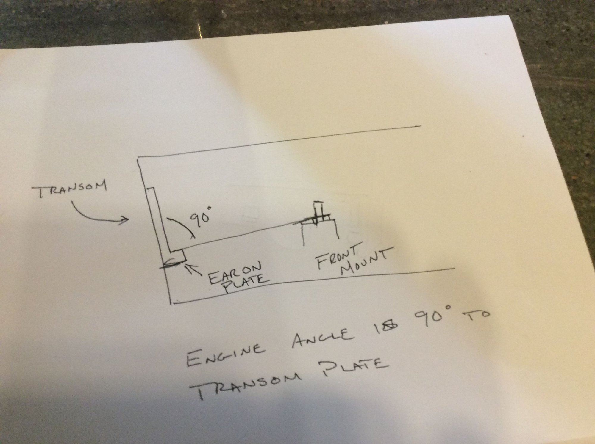
A is from the starboard mount stud to the port transom plate bolt and B is the opposite. C and D are between straight edges laid across front mounts and rear mounts.
A is from the starboard mount stud to the port transom plate bolt and B is the opposite. C and D are between straight edges laid across front mounts and rear mounts.
03-11-2020 | 03:46 PM
#10
Registered
Joined: Feb 2009
Posts: 8,356
Likes: 1,515
From: NW Michigan
Sorry to hear about your issues. That sucks but certainly not the first time for something like this. Like phragle mentioned nothing truly square in a wooden or glass etc boat. I might not be getting a 100% but can you shim anywhere to find a happy medium. My biggest concern would be the potential stress on the side load of seals / bearings. I might have missed it but if you drop your transom mount bolts in place from what I understand is your engine is not parallel to your stringers resulting in not mating with the front mounts. If you can get the drive on without force is it possible to do as motioned above with shimming or offsetting forward mounts. Kinda funny I've used a drywall square myself in the bilge for various reasons over the years but typically leaves me scratching my head for reasons like phragle said.

