

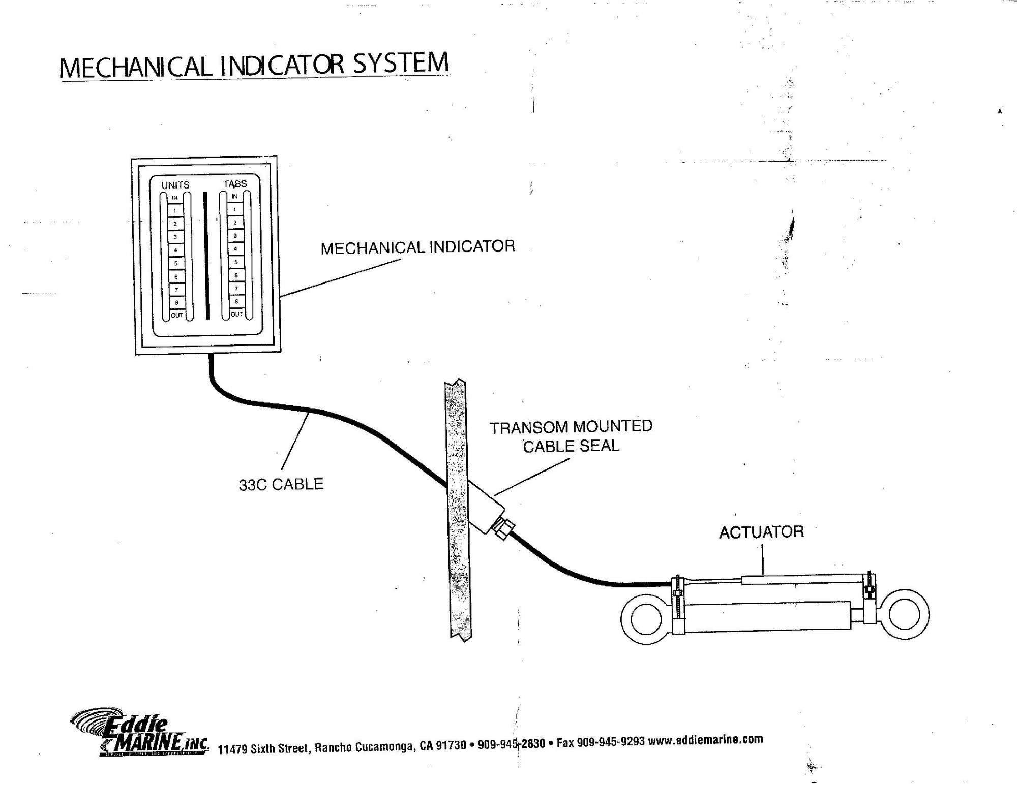
Mechanical drive indicators installation help
 04-21-2023 | 02:14 PM
#1
Thread Starter
Registered
Joined: Jan 2022
Posts: 714
Likes: 209
From: West Michigan
I am now on what I think is my last project before putting the boat in the water. I bought through Eddie Marine a complete install kit for the mechanical drive indicators. The info that came with it isn't really helpful. I do have an email request in to them but I thought I would check with you guys too. I looked on youtube and found one guy that had my kit but he didn't show how he figured where and how to drill the transom. My assumption is that it would be nice to keep that piece above the waterline but probably not necessary? Do you install this piece to the transom and then use it as a guide to drill the hole through the transom? I assume it doesn't matter if I install the mechanical parts on the drives on the inside, outside, or one of each? I have so much sh!t attached to the transom that its going to be a struggle to find room. Thanks for your input.

 04-21-2023 | 03:21 PM
#2
Were doomed!

Joined: Oct 2000
Posts: 7,103
Likes: 1,397
From: Chicago, IL
You can use that as a guide after you install it....ive done it that way once. Make sure to take the plastic or rubber compression fitting inside there out or you will have sealing problems! You can also wrap the drill bit in some tape to help take up any extra space between the fitting and the drill bit when you are drilling so it doesn't chew the fitting up...Start a pilot hole then take everything off and finish drilling it completely through.....then seal it all up with 4200 or some other good sealant and you should be fine.
As far as placement....are these the kind that mount to the drive housing or onto the rams? I guess it really doesn't matter as i've seen these things placed all over the place(above and below the waterline)......depends on if you have enough cable to spare to route it the way you want to.
As far as placement....are these the kind that mount to the drive housing or onto the rams? I guess it really doesn't matter as i've seen these things placed all over the place(above and below the waterline)......depends on if you have enough cable to spare to route it the way you want to.
__________________
-Wally
Money can't buy happiness, but it can buy horsepower. And I've never seen a sad person hauling a$$!
-Wally
Money can't buy happiness, but it can buy horsepower. And I've never seen a sad person hauling a$$!
Last edited by Wally; 04-21-2023 at 03:23 PM.
04-22-2023 | 07:07 PM
#3
Registered

Joined: Nov 2008
Posts: 49
Likes: 6
From: Lake Isabella, Michigan
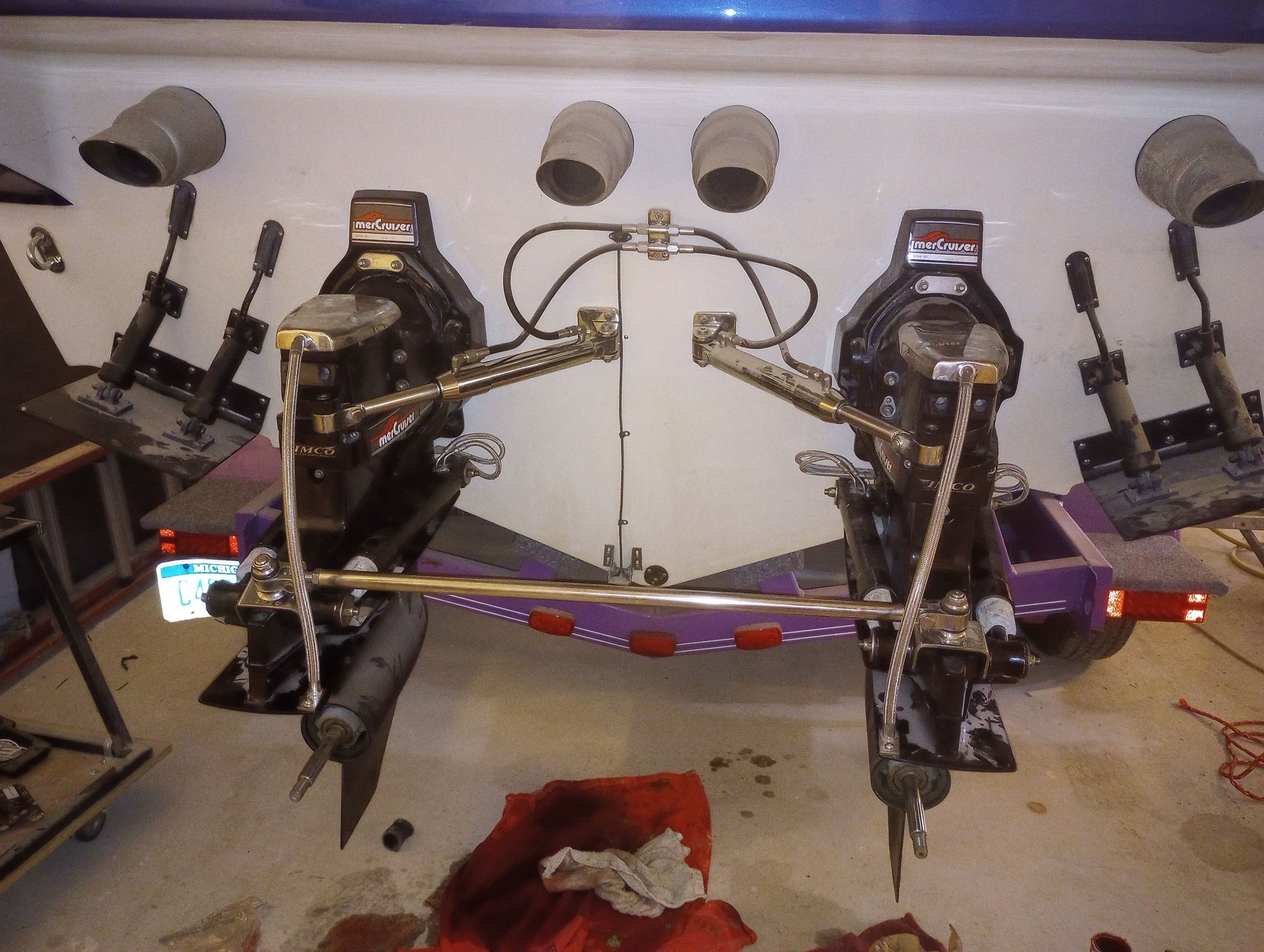
Hi pq, a pic of the actuators/ location of cable seals. When trim is at 0, cable is straight into indicator cable holder. Actuators are from stainless marine. Where in west MI are you? Todd 989-289-9240


04-22-2023 | 11:16 PM
#4
Thread Starter
Registered
Joined: Jan 2022
Posts: 714
Likes: 209
From: West Michigan
Hey Todd, You have a different setup than I do. I bought the part that attaches to the ram so the cable has to make a 90 degree turn up through the transom. I was wondering how far up the transom should the mount be located.
04-26-2023 | 10:18 AM
#6
Thread Starter
Registered
Joined: Jan 2022
Posts: 714
Likes: 209
From: West Michigan
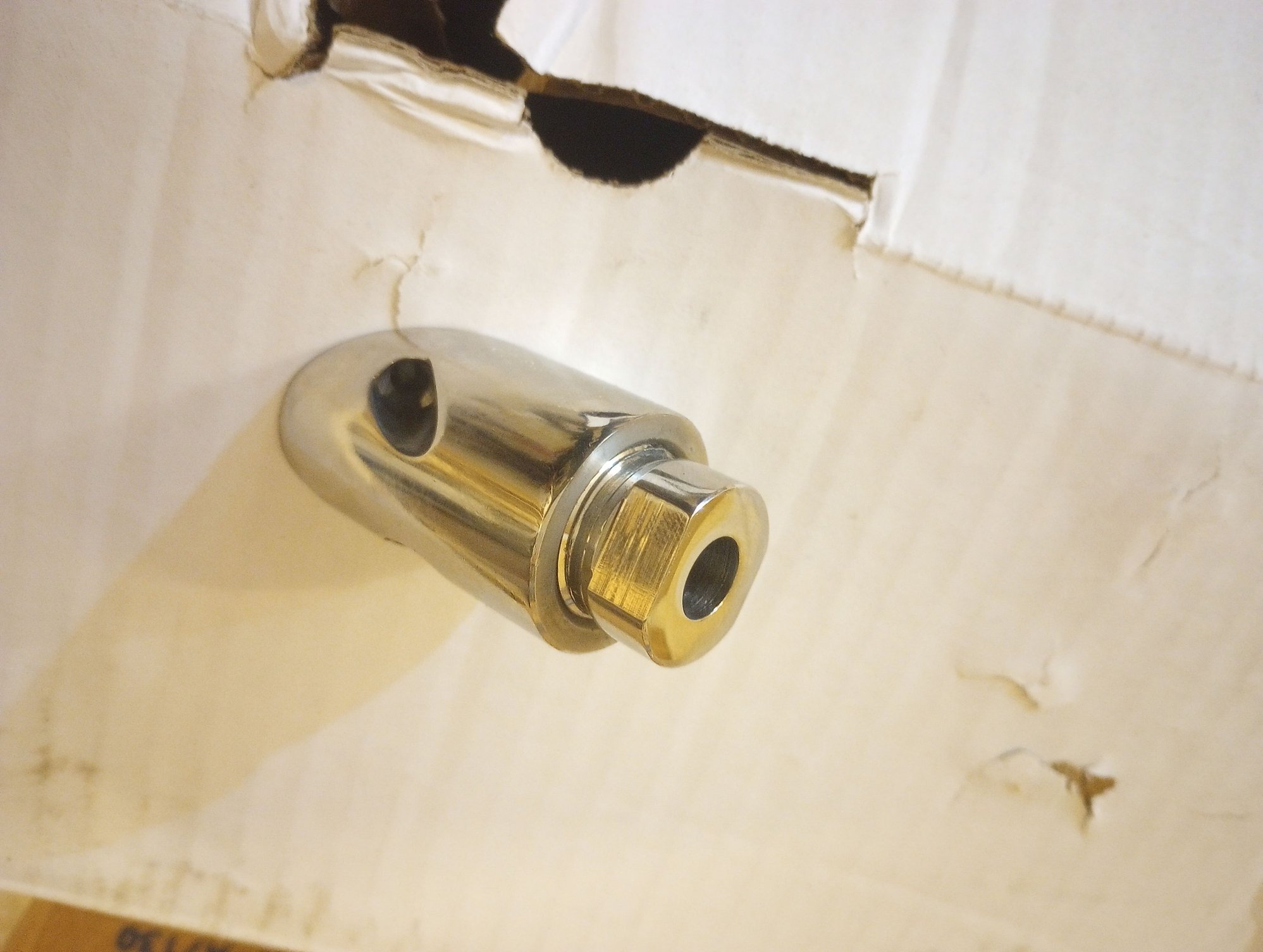
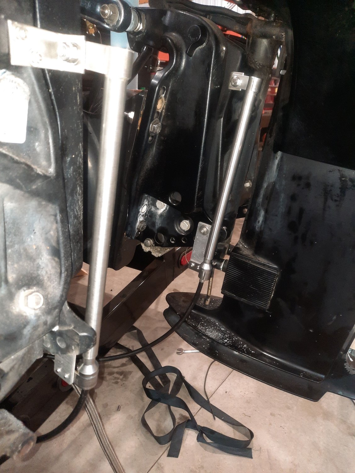
I have a call in to Eddie Marine for some help but again, I thought I would ask here too. I am hoping someone has this system and can tell me the correct sequence for these parts. I was able to attach the through transom pieces without incident. I have the cable stuck through and ready to assemble and install the actuator parts. I have attached a couple pics. The one pic is of the parts that came with the cables and I need to know if these go back on too. There is only one video on youtube and he doesn't explain really anything and I also think his kit is different than mine. Thanks again for your help.


04-26-2023 | 01:44 PM
#7
Registered
Joined: Nov 2008
Posts: 49
Likes: 6
From: Lake Isabella, Michigan
Maybe like this. Put nut on tube, push cable thru nut/tube till end emerges, place slotted washer over slot in cable end, slide in tube a couple of inches, slide spring over cable, compress spring, screw black plunger on cable end, release spring, slide into tube, sinch cable with set screw. Mount to cylinder, mount ring to ram nut.
The diagram you have is for actuators like second pic that clamp to cylinder and ram modified for outboard use. Your new one clamps to cylinder only. On yours the Plunger bumps against bushing attached to ram mount nut. Not sure where the big slotted disk goes. Small boots and nut are for cable and may or may not be able to use them depending how it goes. Sorry about the sticky note shop drawings.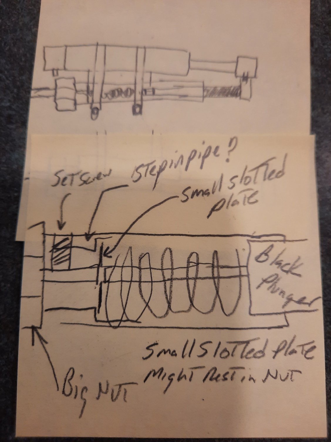
The diagram you have is for actuators like second pic that clamp to cylinder and ram modified for outboard use. Your new one clamps to cylinder only. On yours the Plunger bumps against bushing attached to ram mount nut. Not sure where the big slotted disk goes. Small boots and nut are for cable and may or may not be able to use them depending how it goes. Sorry about the sticky note shop drawings.


