

Gimbal bearing question is it spherical?
 06-27-2023 | 08:12 AM
#1
Thread Starter
Registered
Joined: Jul 2020
Posts: 323
Likes: 55
From: Cortlandt Manor NY
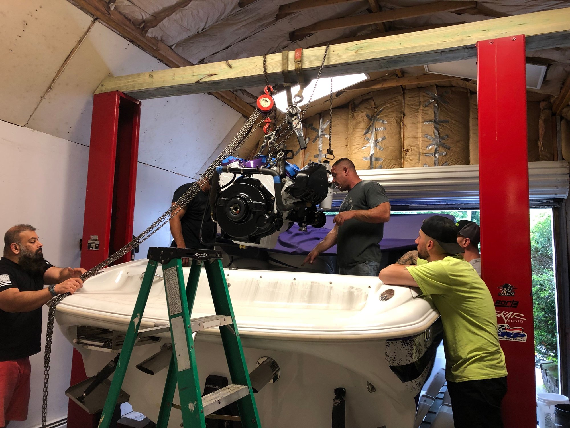
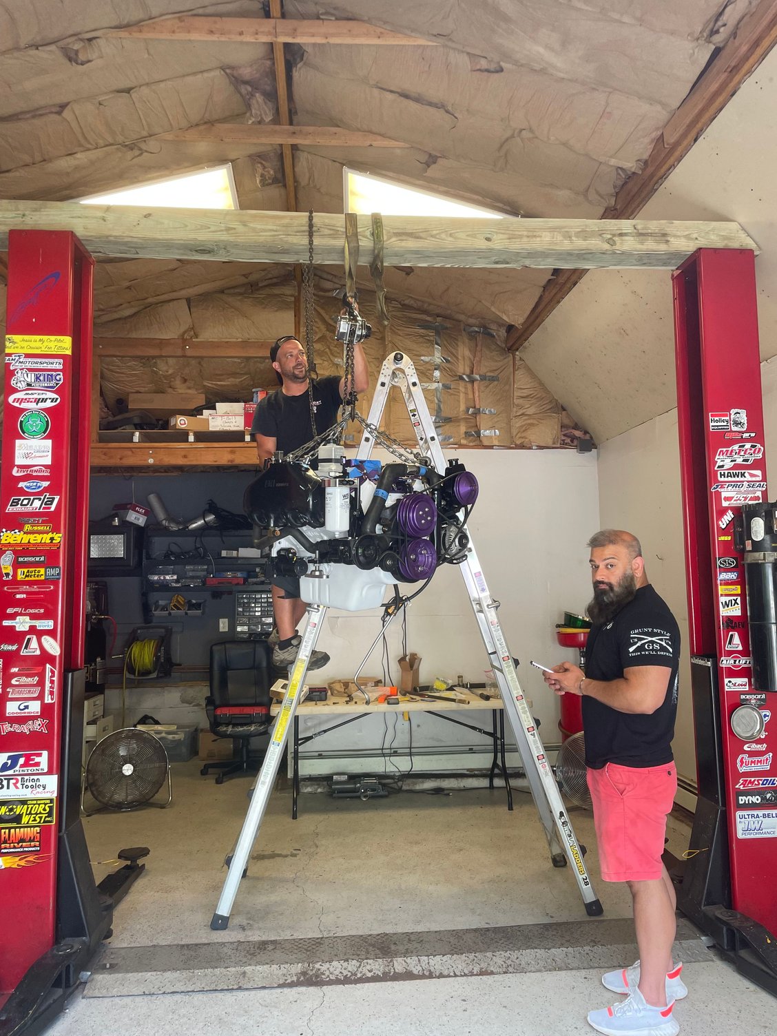
So this past weekend we installed my fresh 509 into my 96 Baja 252 and alng with this it has a brand new Bravo HP transom assembly. For 2hrs we played with alignment and it just would not come into spec the alignment tool was hitting slightly to high and off to one side. When we started to get it in the motor was just not straight and the tool bound up slightly. In the process of pulling it back out I saw the inner race of the bearing move like it was spherical. We were able to reset the engine straight on the rear mounts and now the tool slides in like BUTTER!
My question is was something off and did I wreck the bearing or does the inner race move around on a gimbal bearing? I saw no way for it to go in until this moved and you can take the tool in and out with 2 fingers now.
My question is was something off and did I wreck the bearing or does the inner race move around on a gimbal bearing? I saw no way for it to go in until this moved and you can take the tool in and out with 2 fingers now.
 06-27-2023 | 08:43 AM
#2
Platinum Member

Joined: Feb 2001
Posts: 4,303
Likes: 1,459
From: Virginia Beach
The inner ring/race of the bearing spins. If it is well packed, it should have noticeable resistance.
A lot of the time, the bearing itself can be cocked to one side or the other. If you move the tool, the assembly will also move (up/down/left/right).
A lot of the time, the bearing itself can be cocked to one side or the other. If you move the tool, the assembly will also move (up/down/left/right).
06-27-2023 | 08:58 AM
#4
Thread Starter
Registered
Joined: Jul 2020
Posts: 323
Likes: 55
From: Cortlandt Manor NY
I know a pillow block bearing the center race not only spins but it has a little bit of spherical motion as well I was curious if a gimbal bearing is similar.
06-27-2023 | 09:04 AM
#5
Thread Starter
Registered
Joined: Jul 2020
Posts: 323
Likes: 55
From: Cortlandt Manor NY
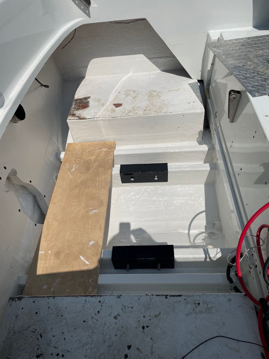
When the tool slid through it was hitting the engine coupler more towards the port side and on the upper side of the coupler. After 2 hrs of playing with it we found the tool can change the angle of the bearing center then it went right in. we also sat the engine down with those spring looking sleeves between the transom assembly bracket and bell housing without tightening the nuts and wouldn't go. Tightened down the nuts and slide right in! This is my first time aligning an engine so it was a trial & error and I just want to be sure I didn't make an error LOL

 06-27-2023 | 12:52 PM
#8
Registered

Joined: Aug 2010
Posts: 1,386
Likes: 565
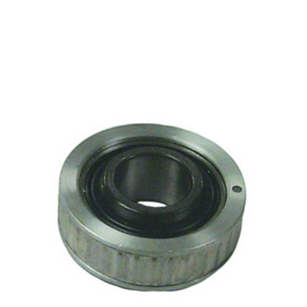
Matter of fact there are 2 grooves in the aluminum outer ring for the bearing "insert" to be installed.
They should face in towards the engine as per the service manual.
But the street trick is to install the bearing "backwards" so any further service you just spin the bearing insert in the aluminum and spin the new one in without any slide-hammer or beating the new bearing in.
Pictures below. The dot should face out, but no notches. The backside, notches.
 06-27-2023 | 01:11 PM
#9
Thread Starter
Registered
Joined: Jul 2020
Posts: 323
Likes: 55
From: Cortlandt Manor NY
They are.
Matter of fact there are 2 grooves in the aluminum outer ring for the bearing "insert" to be installed.
They should face in towards the engine as per the service manual.
But the street trick is to install the bearing "backwards" so any further service you just spin the bearing insert in the aluminum and spin the new one in without any slide-hammer or beating the new bearing in.
Pictures below. The dot should face out, but no notches. The backside, notches.


