

Closed cooling conversion setup
 05-30-2023 | 07:36 PM
#21
Thread Starter
Registered

Joined: Sep 2014
Posts: 396
Likes: 29
From: Patuxent River, Maryland
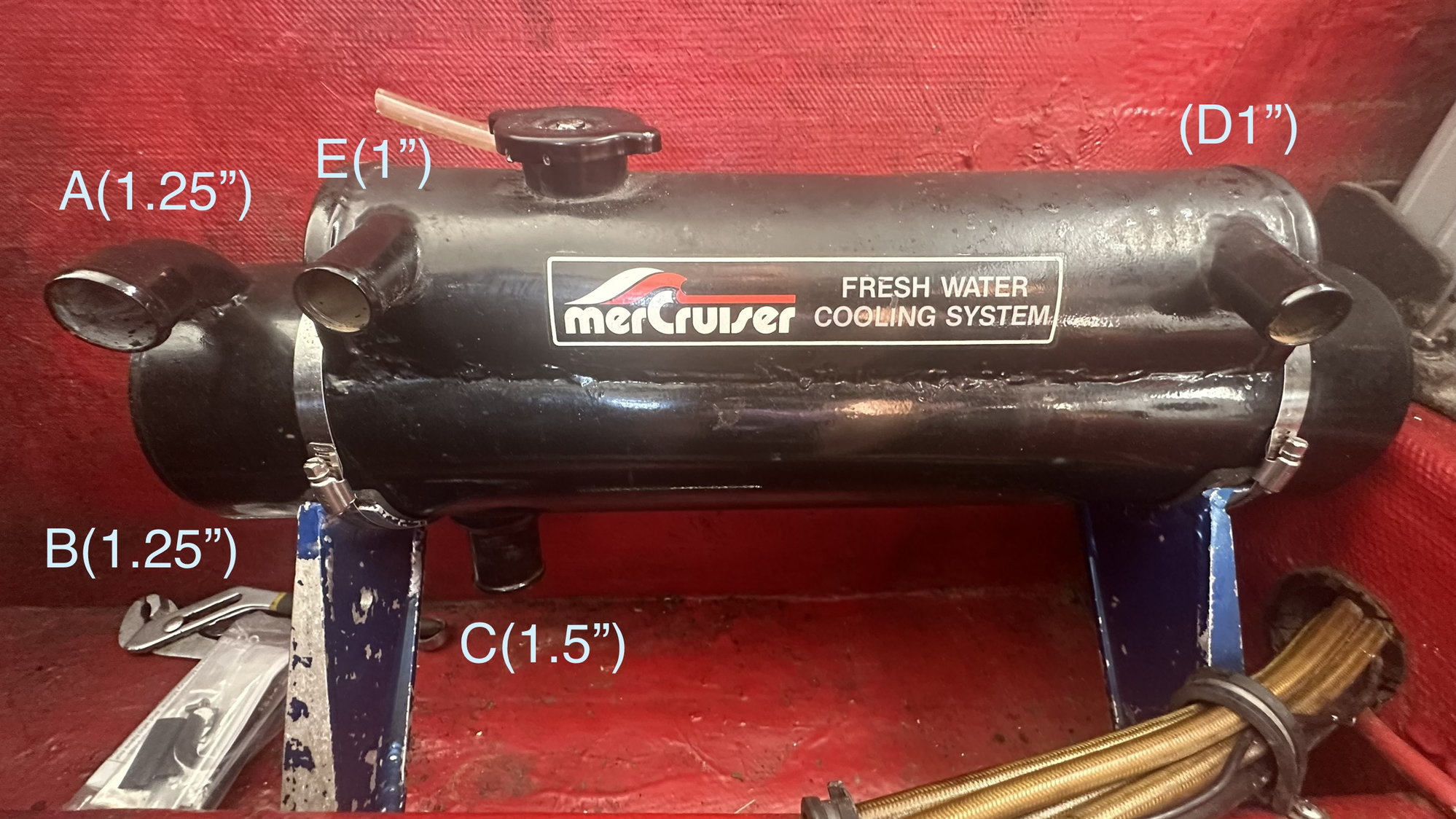
Finally got heads sorted and could get back to the closed cooling setup. All the diagrams ive found show 4 ports but mine have 5. Im thinking maybe because most of them have one raw water outlet which then tees of in the hose to both risers while this one has separate outlets for each?
If thats the case then D and E are raw water outlets to the risers, and im guessing C is the raw water inlet since its about twice the cross sectional area.
Then A and B would be fresh water inlet and outlet, though which is which or does it not matter?
I may be totally off though, since the biggest coolant port on the engines is the inlet at the circulation pump, so that would point towards C being fresh water out of the heat exchanger.
Can anybody point me in the right direction? Note you can't see B its hidden in the pic on the bottom right of the cooler, and the hose sizes are just my guesstimate. Here's a video of them.
 05-31-2023 | 06:24 PM
#22
Thread Starter
Registered
Joined: Sep 2014
Posts: 396
Likes: 29
From: Patuxent River, Maryland
Poured water into the cap today and was able to figure out that C is one end of the closed cooled loop, D and E are the other.
A and B are the raw water loops.
Im not sure why these have 2 ports on one side of the closed cooled loop but in any case what to do for mine where I just need an in and an out... use a T to combine E and D into one?
A and B are the raw water loops.
Im not sure why these have 2 ports on one side of the closed cooled loop but in any case what to do for mine where I just need an in and an out... use a T to combine E and D into one?
06-02-2023 | 10:59 PM
#23
Registered
Joined: Jun 2013
Posts: 123
Likes: 2
From: Aylett, Virginia
that exchanger may of come off a engine where the manifolds were in the closed loop. so D and E would of come from each manifold. the one I used was the same way. I ended up fabbing a thermostat housing that had two inlets instead of a inline tee so it would look nice. IMHO having the exchanger mounted on the hull looks very tacky. plus it makes more work removing the engine. when you mount it on the engine and have some clean plumbing it really looks cool all tight against the engine.
Last edited by 250ekelly; 06-02-2023 at 11:03 PM.
06-03-2023 | 09:48 PM
#24
Thread Starter
Registered
Joined: Sep 2014
Posts: 396
Likes: 29
From: Patuxent River, Maryland
that exchanger may of come off a engine where the manifolds were in the closed loop. so D and E would of come from each manifold. the one I used was the same way. I ended up fabbing a thermostat housing that had two inlets instead of a inline tee so it would look nice. IMHO having the exchanger mounted on the hull looks very tacky. plus it makes more work removing the engine. when you mount it on the engine and have some clean plumbing it really looks cool all tight against the engine.

Last edited by blown; 06-03-2023 at 09:49 PM. Reason: added diagram


