

Nose cone removal
 08-22-2023 | 03:43 PM
#31
Thread Starter
VIP Member

Joined: Jul 2009
Posts: 783
Likes: 51
From: NJ
Thanks My First Time LOL...As for the tube in the front. cut it flush. then crimp it and seal it?
 08-22-2023 | 05:45 PM
#32
Registered


Joined: Aug 2019
Posts: 1,224
Likes: 415
From: BC
That way you can use the tube to flush out any metal filings etc from your work.
Large front tube...if it was me, I would likely clean it up the aluminum and weld it back up using a piece to cover the hole.
Without the equipment and costs, and not seeing it first hand. It's difficult to suggest a solution. Assuming the tube is aluminum? Or something like that?
Trying to get enough material (epoxy style JB Weld) in behind the opening to resist the hydro forces may block the water inlet flow in the hollow passage.
08-22-2023 | 06:10 PM
#34
Thread Starter
VIP Member
Joined: Jul 2009
Posts: 783
Likes: 51
From: NJ
Before doing anything with the tube...I would open up the original water inlets. There are some good threads on the newer style and hole size/placement.
That way you can use the tube to flush out any metal filings etc from your work.
Large front tube...if it was me, I would likely clean it up the aluminum and weld it back up using a piece to cover the hole.
Without the equipment and costs, and not seeing it first hand. It's difficult to suggest a solution. Assuming the tube is aluminum? Or something like that?
Trying to get enough material (epoxy style JB Weld) in behind the opening to resist the hydro forces may block the water inlet flow in the hollow passage.
I will not be using that water port anymore.. I will being opening all the holes on the sides of the drive where the original water inlets were.
08-22-2023 | 06:30 PM
#35
Registered
Joined: Aug 2019
Posts: 1,224
Likes: 415
From: BC
How far in does the tube go before it opens up into the water gallery? (The water passage inside the drive that feeds the impeller.)
Trying to plug the pipe after cuttting it flush at the taper, you may get some JB weld or whater you use out of the pipe inside and block the water flow from the newly opened water inlet. For that matter, the pipe itself may be a flow obstruction.
08-22-2023 | 06:43 PM
#36
Thread Starter
VIP Member
Joined: Jul 2009
Posts: 783
Likes: 51
From: NJ
Trying to plug the pipe after cuttting it flush at the taper, you may get some JB weld or whater you use out of the pipe inside and block the water flow from the newly opened water inlet. For that matter, the pipe itself may be a flow obstruction.[/QUOTE]
I have no idea how far that tube goes in. Its sticks out about an inch. How big is the water passage in the drive. Should I remove the pipe completely? then what? How do I seal up the drive. I should have left the nose cone on. Lesson learned again.. Anyone have a bare case. The other nose cone is staying on for now.
Last edited by 35fountain; 08-22-2023 at 06:45 PM.
08-22-2023 | 08:23 PM
#38
Registered
Joined: Aug 2019
Posts: 1,224
Likes: 415
From: BC
ne
You need to have something to keep the filler in the tube from getting pushed in.
The inside of the tube could be dremel'd up in circles inside, creating a locking ring.
If you cut down the tube on the angle, and cut it a bit deeper than the drove angled surface, the JB weld would have something to hold on to outside the tube. It would also feather out once sanded.
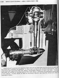
Is the vertical gallery in front of the main shaft for the water? The 8 side holes would line up with that.
Hard to find cutaway photos of the Bravo 1.
08-23-2023 | 05:24 AM
#40
Thread Starter
VIP Member
Joined: Jul 2009
Posts: 783
Likes: 51
From: NJ
I appreciate you want a solution that keeps you on the water until you can focus on it with some breathing room.
ne
You need to have something to keep the filler in the tube from getting pushed in.
The inside of the tube could be dremel'd up in circles inside, creating a locking ring.
If you cut down the tube on the angle, and cut it a bit deeper than the drove angled surface, the JB weld would have something to hold on to outside the tube. It would also feather out once sanded.
Is the vertical gallery in front of the main shaft for the water? The 8 side holes would line up with that.
Hard to find cutaway photos of the Bravo 1.
Another idea. I open all holes up and the cut the nose cone where the pipe goes into. Have a shop weld the other side of the piece cut and use this as a cap for the drive.This way the hydro forces cannot push anything back in.
I could also plug the tube with some kind of threaded pipe plug them marine tex it or flare out the pipe if it's aluminum so it grabs onto the drive. This will hold it in place.
Last edited by 35fountain; 08-23-2023 at 05:39 AM.


