

40' Outlaw Upgrades - Twin 900Sc to 1000hp Duramax Diesels
 05-15-2021, 11:21 AM
#1201
So prop height is limiting your X in the up, leaving w/ 6 degrees shaft angle.
I'd trust the driveshaft guy If he knows the weight-torque&rpm involved with that 6 degrees continuous load if he says you'll be fine.
Bet that drive trims in more than enough and will still get 5-6 degrees of "in"after your boxes.
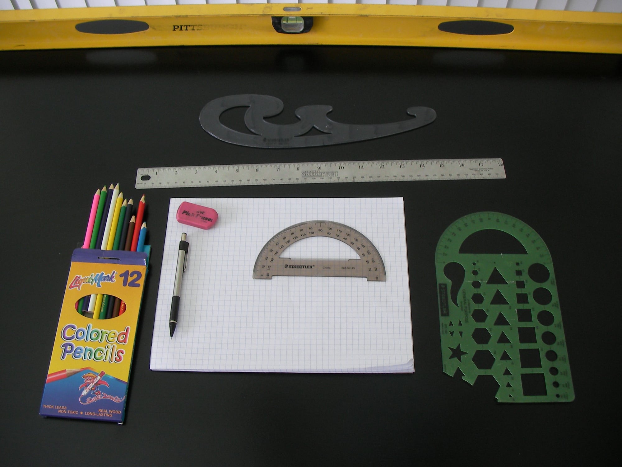
i see you use grid paper and colored pencils for the really important stuff too !
I'd trust the driveshaft guy If he knows the weight-torque&rpm involved with that 6 degrees continuous load if he says you'll be fine.
Bet that drive trims in more than enough and will still get 5-6 degrees of "in"after your boxes.
i see you use grid paper and colored pencils for the really important stuff too !
Last edited by outonsafari; 05-15-2021 at 11:26 AM.
 05-16-2021, 11:14 PM
#1202
Registered
Thread Starter
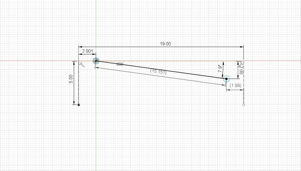
The colored pencils and protractor keep telling me this chit is gonna be close even after raising the boxes 2 inches. That new 19" driveshaft estimate just lost 2" off each end after checking the 1480 U-joint flanges dimensions. See pic.
That brings our actual length between pivot points down to 15 inches again, and pushes past 8deg of normal operating angle. According to Spicer specs, no chance of binding, but U-joint life is halved at our torque and operating RPM. Luckily the math says they should still be good for around 1000hrs, greased often. Adding 2 inches to the extension boxes only gains us 1deg in shaft operating angle. Here is link to a good doc from Spicer showing all the shaft options, and how to calculate all the crazy math involved.
https://d3qx1uccksbb2n.cloudfront.net/docs/ij900-81.pdf
The following users liked this post:
2187 (05-17-2021)
05-17-2021, 11:13 AM
#1204
The colored pencils and protractor keep telling me this chit is gonna be close even after raising the boxes 2 inches. That new 19" driveshaft estimate just lost 2" off each end after checking the 1480 U-joint flanges dimensions. See pic.
That brings our actual length between pivot points down to 15 inches again, and pushes past 8deg of normal operating angle. According to Spicer specs, no chance of binding, but U-joint life is halved at our torque and operating RPM. Luckily the math says they should still be good for around 1000hrs, greased often. Adding 2 inches to the extension boxes only gains us 1deg in shaft operating angle. Here is link to a good doc from Spicer showing all the shaft options, and how to calculate all the crazy math involved.
https://d3qx1uccksbb2n.cloudfront.net/docs/ij900-81.pdf
the boxes would have to be enlarged down and to the shape of the hull to start transfering the loads
(port and strbrd shaped box ) so basically every 1 solution must be adjusted to keep 2, 3, or 4 other things in spec.
i know you have things well in hand, that's obvious. You proved the concept, ran the boat, it performed well, there literally is "more there".
certain design flaws in parts you cannot control have you where your at, from what i see and read, and i only understand a 10nth of it, you are at a pivotal moment.
Last edited by outonsafari; 05-17-2021 at 11:15 AM.
05-18-2021, 12:01 AM
#1205
Registered
Thread Starter
Then there is about 4" height difference, and 10" depth difference between where drive side flange was at on the W's compared to the 6's. We actually used that 3deg of down angle on engine/trans to compensate that height difference on the W's.. Found my old notes. If not for that, turbos would have been sticking out the hatch with crank centerline 4-5" higher than we are setting now. And in the end, we would be in exact same situation, trying to raise the drive or lower the engines to get our centerlines close enough that our driveshafts don't have stupid angles. Only other option is just remove all the engine mounts and put them back in factory holes, all would be fine. Then all the exhaust and chit gets jacked out of shape, lots more work than anyone wants to consider.
So besides building a 4" jack shaft, making the top of the boxes shorter than bottom, we get our flange angles correct. Difference from stock drive trim is only 3deg at prop end. IF we built say a 20" deep extension box, all would be easy cause shaft angle decreases with length. But while 20" would probably be a bit extreme, playing with 14-15" right now. The box we mocked up was 12" deep, and set our props exact same distance from transom. As where the W boxes were only 8" deep. Ya just have to keep playing with all the numbers till X dim, depth, and angles hopefully land in somewhere happy. Adding an inch here or there, moves X up or down 1/2" and some angle by a degree or two.
Short answer to your question. Not likely, adds more driveshaft angle..
05-18-2021, 12:19 AM
#1206
Registered
Thread Starter
I finally got a template ready to go for the end plates. Gonna cut one outa thin gauge steel to verify the outside edges next week. For transom side, it will use the lower bolt pattern, and drive side will use the upper pattern. 2" difference. Probably add one more set of holes between them just to have another option.
The one option I'm certainly adding I've yet to see in 6 extension boxes is a removable top inspection plate. How they expect ya to grease a joint or tighten a hydraulic line without removing the box is mystery to me.")
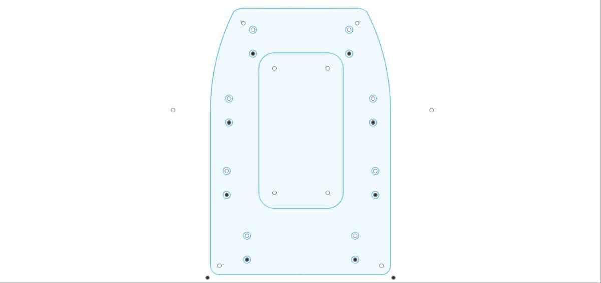
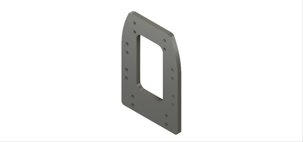
The one option I'm certainly adding I've yet to see in 6 extension boxes is a removable top inspection plate. How they expect ya to grease a joint or tighten a hydraulic line without removing the box is mystery to me.
The following users liked this post:
ksalmine (05-18-2021)
05-18-2021, 12:25 PM
#1207
while driveline geometry is a good rule of thumb, remember that in your drive, both the wesimen and the mercury, the ujoints go out of parrallel and such everytime you trim up or down from neutral and steer right to left or is that port to starboard?
the logical thing to advise is to reposition the engines to the drive for proper alignment. might be the least expsensive route as well. as to the standoff box access cover, they are common on the skater ones i believe.
the logical thing to advise is to reposition the engines to the drive for proper alignment. might be the least expsensive route as well. as to the standoff box access cover, they are common on the skater ones i believe.
05-18-2021, 01:02 PM
#1208
Registered
05-18-2021, 03:17 PM
#1209
yes there is a double cardon on the input shaft similar to the bravo design. the only time the time the ends of the cardon are parallel is when the drive is turned and trimmined within a specific location.
05-19-2021, 12:04 PM
#1210
Registered
My thinking was that moving the drives in board 1� allows you to lower the drive just over 0.5�.
I haven�t drawn it up yet to see if that scenario helps or hurts you in total shaft angle.
I haven�t drawn it up yet to see if that scenario helps or hurts you in total shaft angle.

