

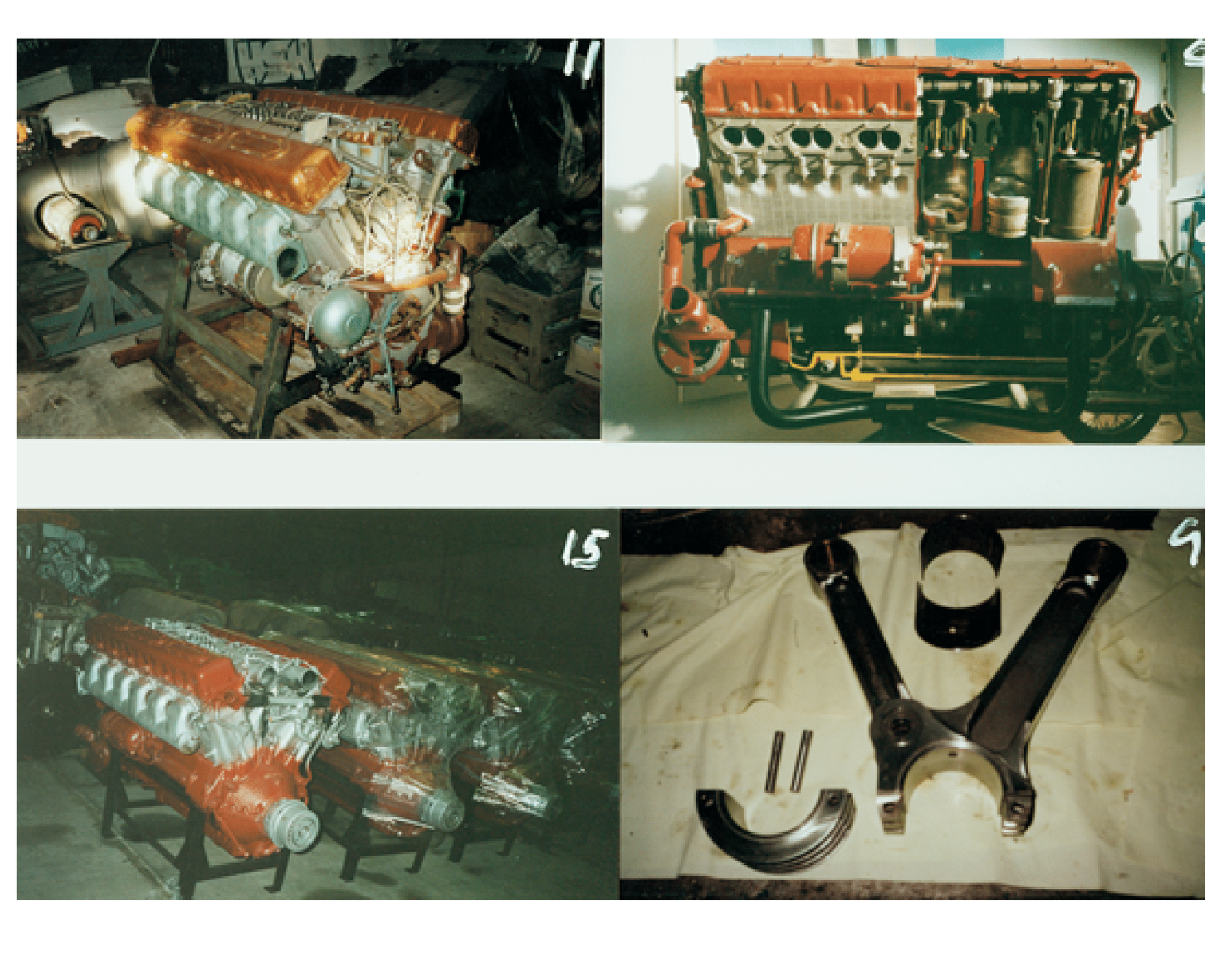
Fountain 47, 2372cid single engine diesel

 01-09-2021 | 01:31 PM
#92
Thread Starter
Registered

Joined: Jan 2010
Posts: 346
Likes: 877
From: Finland
some new parts..
Heat exchanger is ready, it weights only 15kg and IF my calculations is correct, it will be large enough.
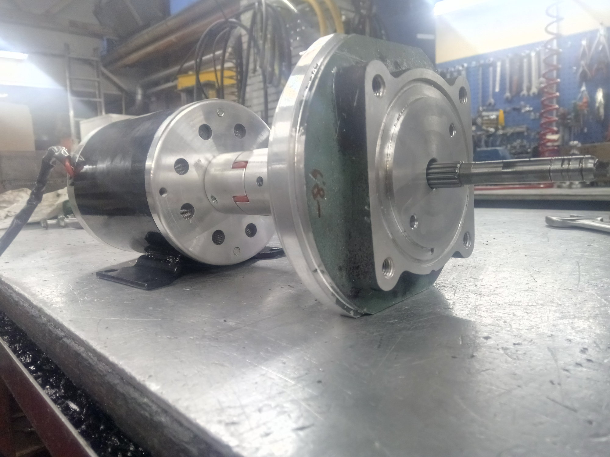
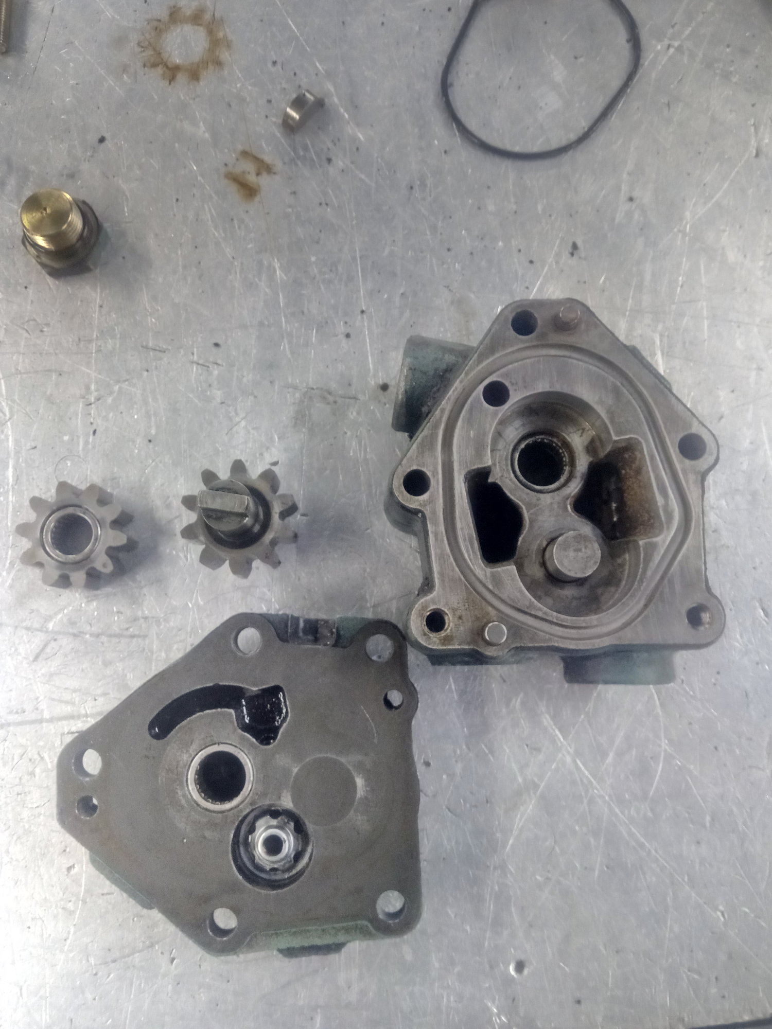
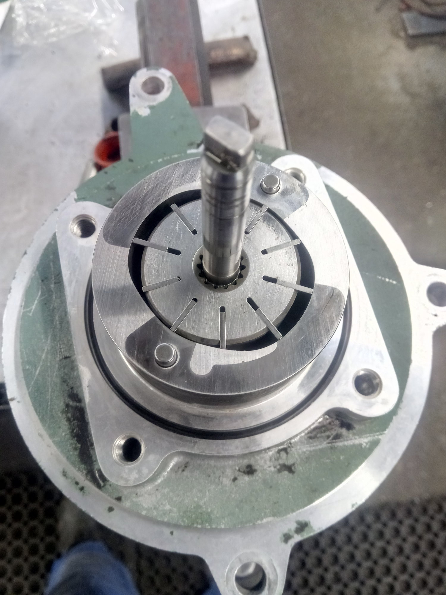
Prelube pump is half ready, need more machining but it can be made that way. Motor is 24VDC 500w, 2500rpm, hope it have enough power to drive double pump. Pump is originally Volvo bus power steering pump with fuel pump in same shaft. vane pump (power steering) drain oil sump, fuel pump make prelube oil pressure. Transmash have to prelube before start because it has no oil feeds in block, all oil go inside hollow crankshaft via rotary connector. When engine is not used for a while, crank drain oil to sump and if engine is started that way, it takes forever to get oil pressure. It will cause bearing damage.
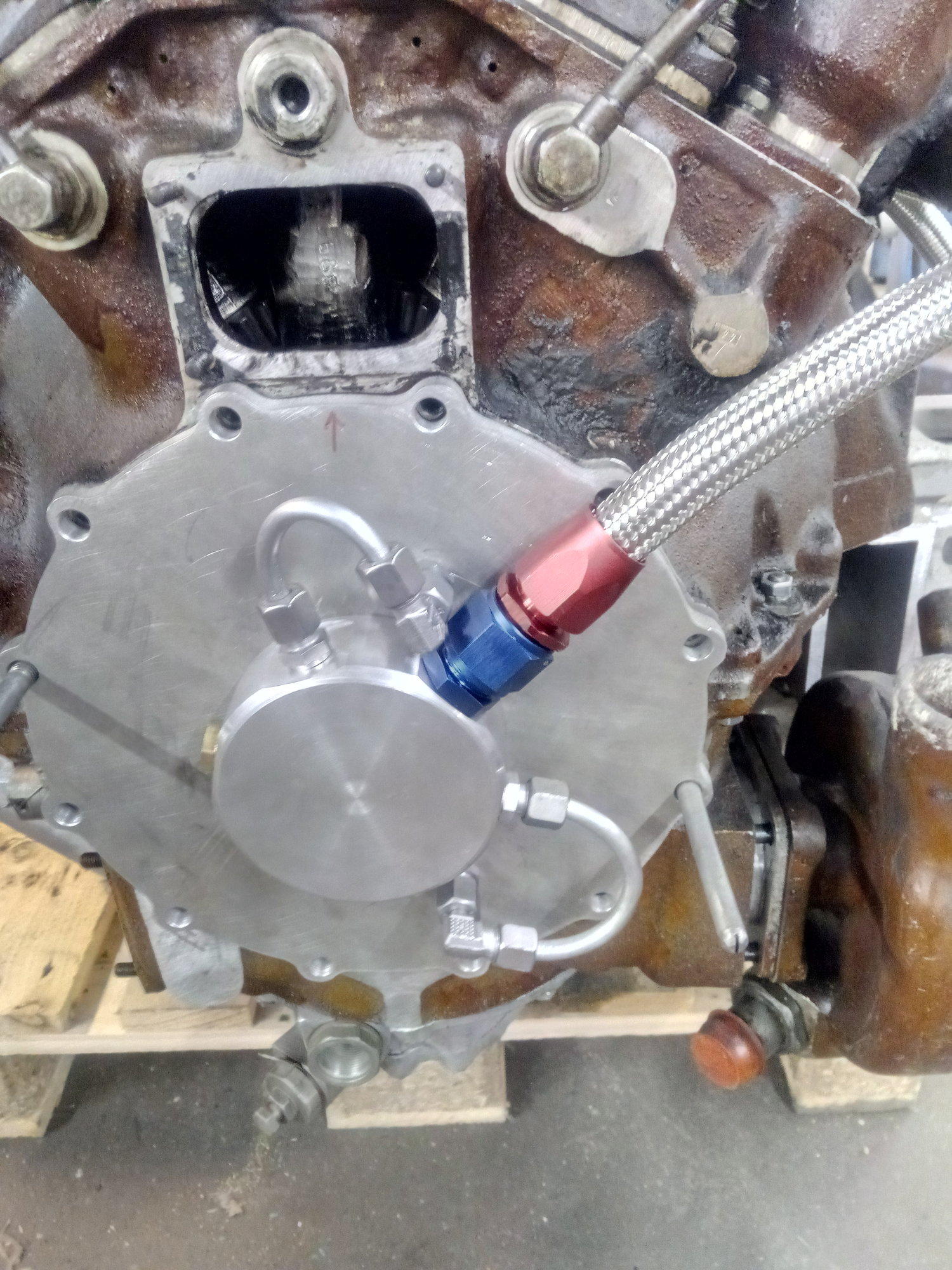
Rotary connector oil supply piece is ready, it feeds also all timing, auxiliary shaftf bearings and valve train lubrication.
Injector pump governor housing had tiny oil leak, housing was bend a little bit after welding. It's now grind straight. Governor housing is very difficult to disassembly and put together!


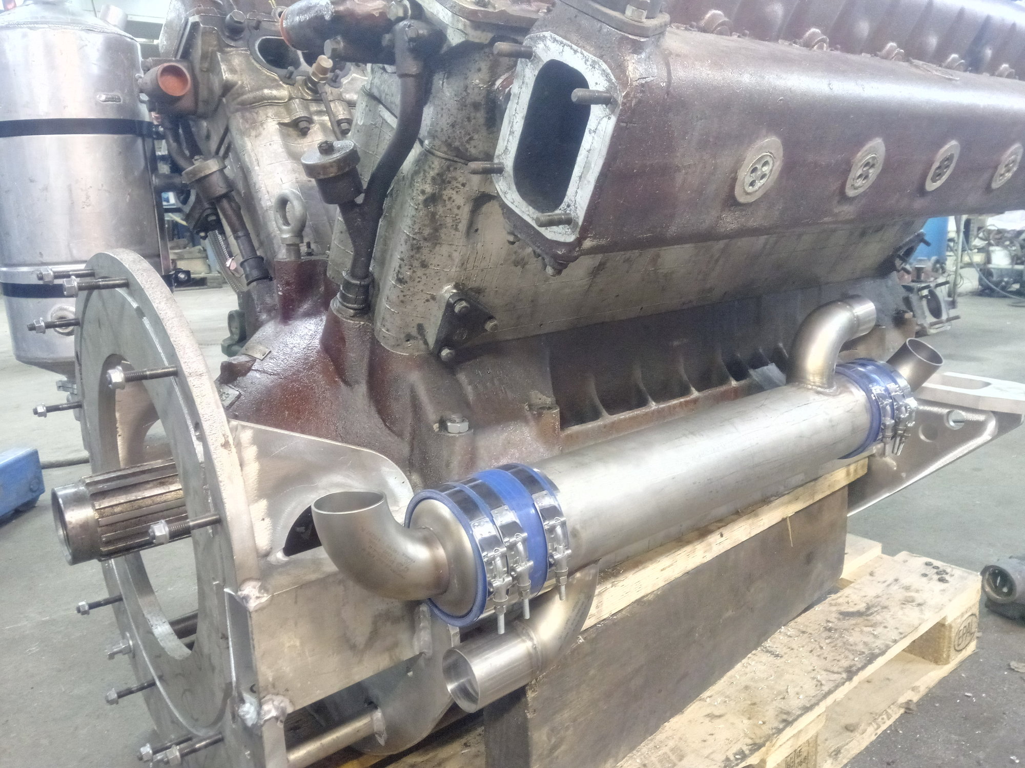

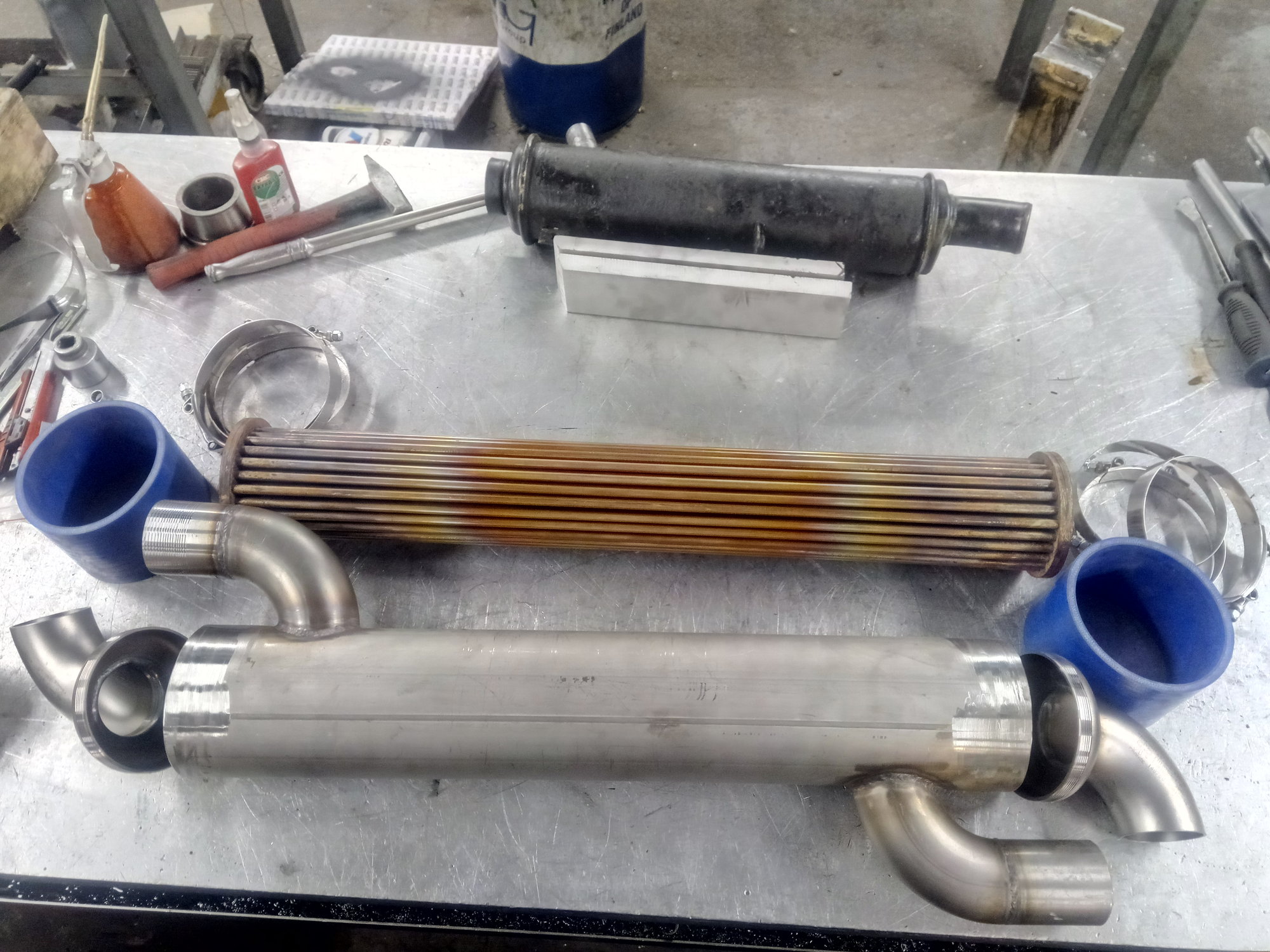
Heat exchanger is ready, it weights only 15kg and IF my calculations is correct, it will be large enough.
Prelube pump is half ready, need more machining but it can be made that way. Motor is 24VDC 500w, 2500rpm, hope it have enough power to drive double pump. Pump is originally Volvo bus power steering pump with fuel pump in same shaft. vane pump (power steering) drain oil sump, fuel pump make prelube oil pressure. Transmash have to prelube before start because it has no oil feeds in block, all oil go inside hollow crankshaft via rotary connector. When engine is not used for a while, crank drain oil to sump and if engine is started that way, it takes forever to get oil pressure. It will cause bearing damage.
Rotary connector oil supply piece is ready, it feeds also all timing, auxiliary shaftf bearings and valve train lubrication.
Injector pump governor housing had tiny oil leak, housing was bend a little bit after welding. It's now grind straight. Governor housing is very difficult to disassembly and put together!
01-09-2021 | 01:44 PM
#93
Registered

Joined: May 2003
Posts: 422
Likes: 55
From: UK, Florida
The generator engine version of this engine uses a rather larger heat-exchanger, keep up the good work looking forward to seeing this in the water, I thought about the same conversion many years ago.

Last edited by 999JAY; 01-09-2021 at 01:48 PM.
 02-05-2021 | 02:13 PM
#95
Thread Starter
Registered
Joined: Jan 2010
Posts: 346
Likes: 877
From: Finland
Raw water is 20degreeC and coolant from engine is 90 degreeC, temperature differrence define cooler size.
02-05-2021 | 03:16 PM
#96
Thread Starter
Registered
Joined: Jan 2010
Posts: 346
Likes: 877
From: Finland
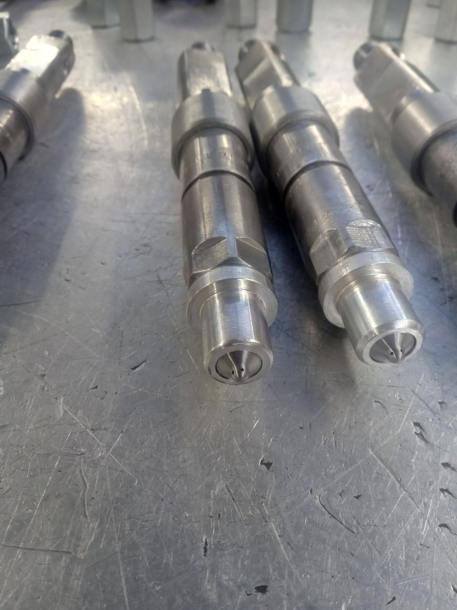
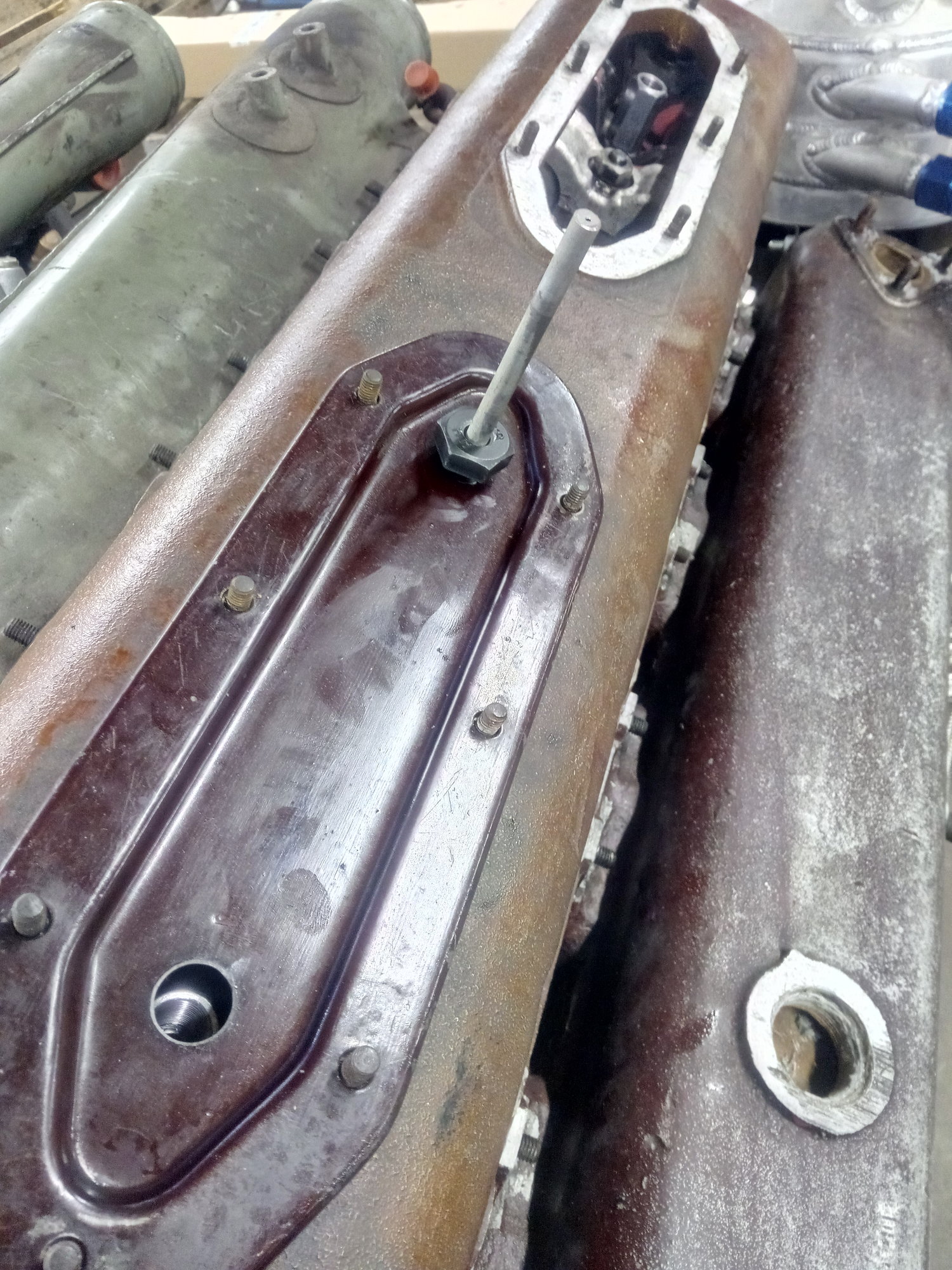
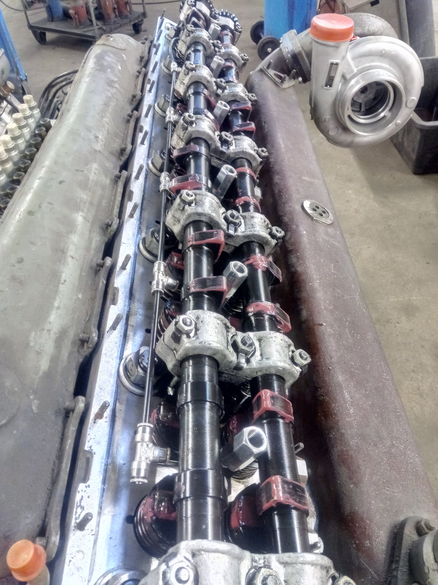
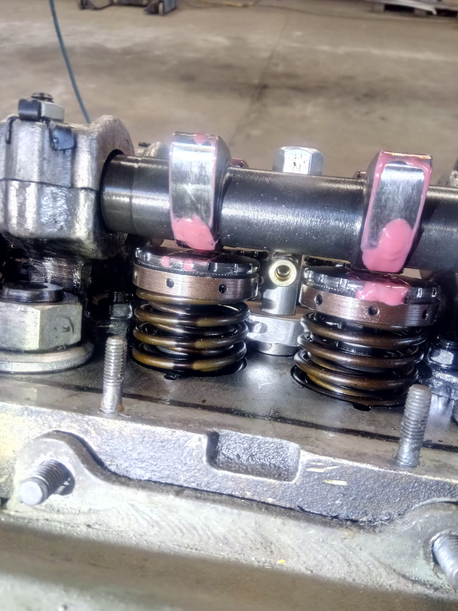
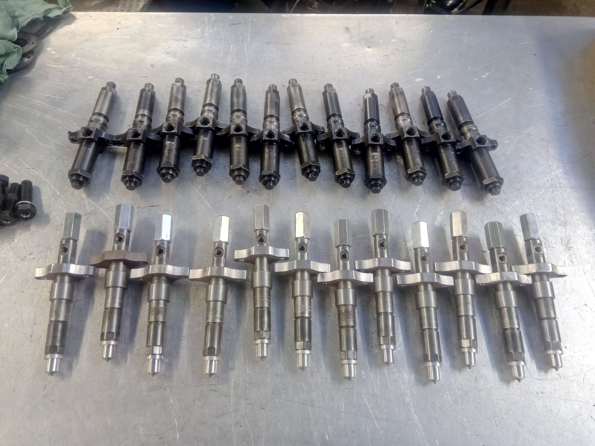
Some update for a long time. Finaly I found a company that can make custom injector lines. 8mm pipe, 3mm hole that is only way to go. I will make mock up lines at basic hydraulic pipe so remain lines is easier bend to right form. Original injectors are side feed, bosch ones are top feed so I have to modify valve cover plates for new lines.
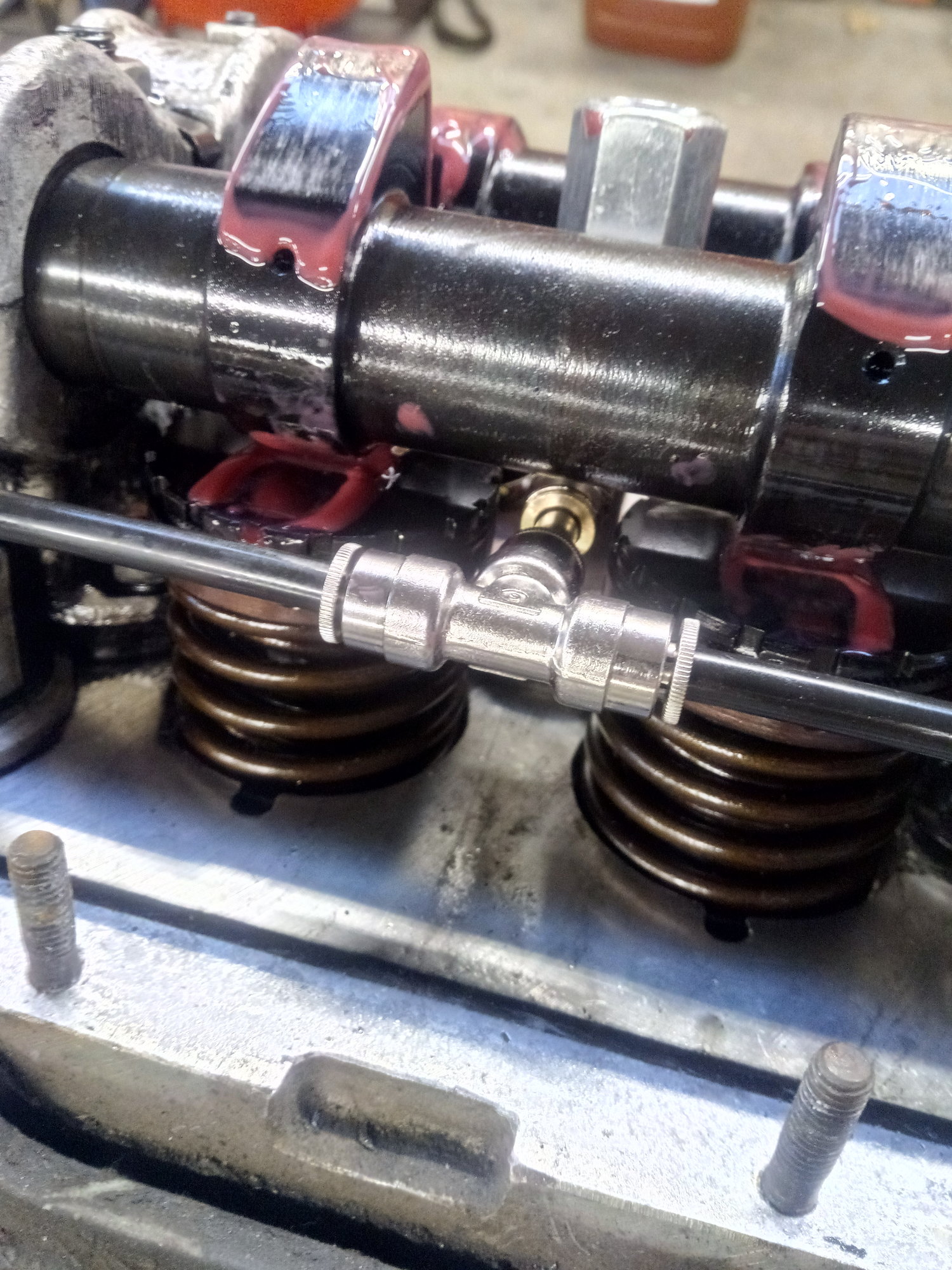
Stock injectors off, custom ones in. There is absolutely no free space between valves and cams. Bleed line fittings can't be assembled before injectors are in place.
Nozzle hole size is comic
First start isn't so far away....

Stock injectors off, custom ones in. There is absolutely no free space between valves and cams. Bleed line fittings can't be assembled before injectors are in place.
Nozzle hole size is comic
First start isn't so far away....
02-14-2021 | 03:33 AM
#97
Thread Starter
Registered
Joined: Jan 2010
Posts: 346
Likes: 877
From: Finland
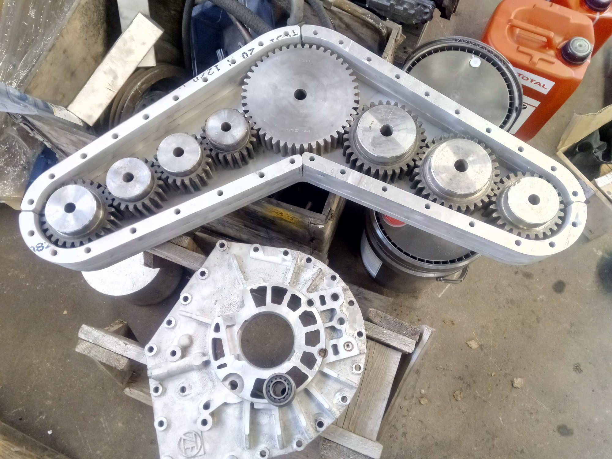
I made calculations for splitbox, it can handle 10.000Nm so that doesn't lose teeth. Wear will be another story, C45 steel is't strongest, about 800Mpa, but industrial spur gear blanks are cheap way to make prototype. Smaller gears are induction hardened, center gear isn't, It must harden after machining. Case is made 20mm sheet aluminium by water cut, billet case would be better but this design allow change gear ratio so that center case could re-use. If ratios are ok, but wear is problem I make new billet one with better gears.
Ratio is 0.5555:1, engine speed is 2400rpm, fourth gear are straight 1:1, so prop shafts run 4320rpm. That's same than 6500rpm gas engine with 1.5:1 outdrive.
I have 16.5x34" four blade rolla props, calculations give 125mph top speed at 10% slip. Props spin in. Yes I know 5 or 6 blade 18" would be better, but I don't want spend a lot of money for props yet.
In early 2000 boating magazine they did test to 47 Lightning, twin 1075hp boat, it perfoms best 16.5x36 but rake and number of blades was not told.
I have made research for carbon fiber drive shafts, they allow more flex than steel or aluminium ones, Fountain drive shafts are almoust as long as 47 bilge so I need vibration free drive shafts. Carbon is best material for that. Joints are big 128mm crmo cage CV joints, I hope they survive a violent torque... heat and wear could be issue.
Any experience about CV joints OSO members? I have asked this before, but let's try again.
Another question is drive distance to each other, staggered boats have drives mounted very close of course, but are bigger advantage center of gravity or clear water to props?
If CV joints are 0 degree angle drives will be 32" apart, this is good for few reasons:
1. I don't have to fill whole notch
2. CV joints have less angle so less heat
3. Drive shafts have more clearance to engine
4. Engine could be few inches lower in bilge
What you think? all thing mentioned before go worse if prop goes closer together
02-17-2021 | 08:35 PM
#98
Registered
Joined: May 2009
Posts: 1,942
Likes: 527
Qoute
I have made research for carbon fiber drive shafts, they allow more flex than steel or aluminium ones, Fountain drive shafts are almoust as long as 47 bilge so I need vibration free drive shafts. Carbon is best material for that. Joints are big 128mm crmo cage CV joints, I hope they survive a violent torque... heat and wear could be issue.
Any experience about CV joints OSO members? I have asked this before, but let's try again.
Another question is drive distance to each other, staggered boats have drives mounted very close of course, but are bigger advantage center of gravity or clear water to props?
If CV joints are 0 degree angle drives will be 32" apart, this is good for few reasons:
1. I don't have to fill whole notch
2. CV joints have less angle so less heat
3. Drive shafts have more clearance to engine
4. Engine could be few inches lower in bilge
What you think? all thing mentioned before go worse if prop goes closer together[/QUOTE]
The project looks to be moving along very nicely ! I will attempt to answer your questions by referring to earlier posts and by my interpretation from the above qoute.
post 13 you mentioned filling 6 exhaust holes and 3 outdrive holes.
post 17 it was suggested you where on right path to fill the notch and mount the surface drives as lo as possible.
post 23 a 20 inch drive centerline was mentioned.
post 28 filling the notch was mentioned.
by the looks of the project, all the work you have put in, the level of craftsmanship you have and some other projects you have completed or been involved with (what i gather from reading this thread), my opinion is you know what has to be done but since picking outdrive centerlines and propshaft heights are the hardest decision a man can make in this world, your doubting what you know.
I would put a new transom in and remove the notch and temporarily mount the drives at 20 inches in between and as low on the transom as they could go.
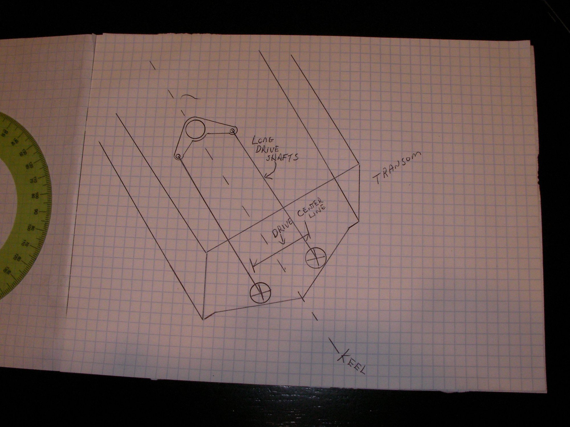
i think your putting the engine in backwards with the split case forward in the engine room with the drive shafts running back the the drives.
the longer shafts will reduce your cv angle.
sorry for the hand drawing, the sand leaked out of my etch a sketch
I have made research for carbon fiber drive shafts, they allow more flex than steel or aluminium ones, Fountain drive shafts are almoust as long as 47 bilge so I need vibration free drive shafts. Carbon is best material for that. Joints are big 128mm crmo cage CV joints, I hope they survive a violent torque... heat and wear could be issue.
Any experience about CV joints OSO members? I have asked this before, but let's try again.
Another question is drive distance to each other, staggered boats have drives mounted very close of course, but are bigger advantage center of gravity or clear water to props?
If CV joints are 0 degree angle drives will be 32" apart, this is good for few reasons:
1. I don't have to fill whole notch
2. CV joints have less angle so less heat
3. Drive shafts have more clearance to engine
4. Engine could be few inches lower in bilge
What you think? all thing mentioned before go worse if prop goes closer together[/QUOTE]
The project looks to be moving along very nicely ! I will attempt to answer your questions by referring to earlier posts and by my interpretation from the above qoute.
post 13 you mentioned filling 6 exhaust holes and 3 outdrive holes.
post 17 it was suggested you where on right path to fill the notch and mount the surface drives as lo as possible.
post 23 a 20 inch drive centerline was mentioned.
post 28 filling the notch was mentioned.
by the looks of the project, all the work you have put in, the level of craftsmanship you have and some other projects you have completed or been involved with (what i gather from reading this thread), my opinion is you know what has to be done but since picking outdrive centerlines and propshaft heights are the hardest decision a man can make in this world, your doubting what you know.
I would put a new transom in and remove the notch and temporarily mount the drives at 20 inches in between and as low on the transom as they could go.
i think your putting the engine in backwards with the split case forward in the engine room with the drive shafts running back the the drives.
the longer shafts will reduce your cv angle.
sorry for the hand drawing, the sand leaked out of my etch a sketch
Last edited by outonsafari; 02-17-2021 at 08:43 PM.
02-18-2021 | 02:37 PM
#99
Thread Starter
Registered
Joined: Jan 2010
Posts: 346
Likes: 877
From: Finland
Thats exactly what I'm doing, engine is front in back, transmission on the bow side. center off gravity goes little back when heavy engine is as close to transom as possible. 6" exhaust is also shorter and lighter. 60mm waste gates will have own 3" tail pipes, Sound may be awesome when ports open, like P51 mustang at full song, love it!
I like put drives closer together but it will raise the engine. Another problem is drive shaft angle, it makes 4 degree difference if drives are closer together like in drawing. It's back view of boat.
Aquadrive, that I won't use, manual says:
Max static torque 6000 Nm 4440 lbft
Max angularity/joint 8000 rpm
0-1400 rpm = 8�
1800 rpm = 6�
3600 rpm = 3�
So 4 degree and 4320rpm at 2000nm is not good. Drives could be mounted maybe 28-30" apart, outer places in drawing is 32.4" and inner 23.2". If there will come some prop slip or other weird problems, let's figure them out then.
Drives are not ASD's, they are self made. Shaft flanges move along trim and steering so drive shafts move little every direction. There must be some clearance to engine frame.
By the way, dimensions in drawing are millimeters.
Carbon drive shafts could be safer than steel or aluminium ones if they broke. Carbon have less inertia energy and after snap it's quite soft so they may not find route through bottom if worst happens. some explosion shields should be done.
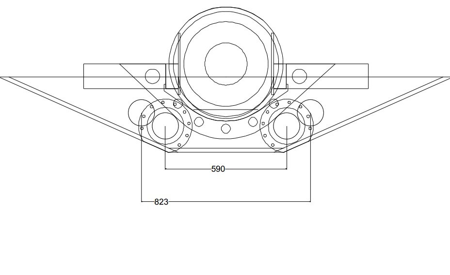
02-18-2021 | 04:07 PM
#100
Registered
Joined: May 2009
Posts: 1,942
Likes: 527
Awesome, engine backwards is the only way to go. I see what you mean about rpm torque and angle.
in that case i would move the drives apart until shaft angle was zero or 1 degree.
side by side engine boats with 34 - 36 centerlines can go 100 mph, so why won't yours if drives centerlines are 32 inches
i would also make sure the transmission and split case can be removed from the boat without remving the engine
seems to me only from reading about other complex hi hp hi torque hi speed projects, the initial problems are always in the transmission and shaft angles are always a concern.
you have a double whammy going on(complex transmission and split case) so make it easy to remove and work on.
i think it will work with minimal shaft angles and you will be happy.
keep up the good work
Last edited by outonsafari; 02-18-2021 at 04:11 PM.

