

Fountain 47, 2372cid single engine diesel
 12-17-2023 | 09:24 AM
#271
Offshoreonly Advertiser

Joined: Mar 2001
Posts: 2,518
Likes: 283
From: Pompano Beach FL, USA
I've been following your thread with great envy! Amazing undertaking.
Hope you don't mind if I pitch in here. Over the years I have made a good number of mufflers using a flapper & shaft. Found that both the shaft and disk would eventually crack. I assume from the constant flexing due to the exhaust impulses.
Finally solved the problem by going to a larger diameter on the shaft and not cutting the flat on it. Then formed the disk around it. I don't remember the exact diam but I have a pair of mufflers at the shop I will measure the next time I'm there. At least .625 (about 16 mm).
I'll post a pic and a sketch of how I formed the disk also.
__________________
Marc
www.mercruiserparts.com
www.go-fast.com
www.bammarine.com
www.cyborgtransmissions.com
It's not alive -www.BoatStuffExpress.com - temporarily retired
Marc
www.mercruiserparts.com
www.go-fast.com
www.bammarine.com
www.cyborgtransmissions.com
It's not alive -www.BoatStuffExpress.com - temporarily retired
 12-17-2023 | 12:48 PM
#272
Thread Starter
Registered

Joined: Jan 2010
Posts: 346
Likes: 874
From: Finland
I live in Valkeakoski, we can make some films after I can transfer Fountain in home garage. it would be nice!
12-17-2023 | 01:03 PM
#273
Thread Starter
Registered
Joined: Jan 2010
Posts: 346
Likes: 874
From: Finland
I've been following your thread with great envy! Amazing undertaking.
Hope you don't mind if I pitch in here. Over the years I have made a good number of mufflers using a flapper & shaft. Found that both the shaft and disk would eventually crack. I assume from the constant flexing due to the exhaust impulses.
Finally solved the problem by going to a larger diameter on the shaft and not cutting the flat on it. Then formed the disk around it. I don't remember the exact diam but I have a pair of mufflers at the shop I will measure the next time I'm there. At least .625 (about 16 mm).
I'll post a pic and a sketch of how I formed the disk also.
Hope you don't mind if I pitch in here. Over the years I have made a good number of mufflers using a flapper & shaft. Found that both the shaft and disk would eventually crack. I assume from the constant flexing due to the exhaust impulses.
Finally solved the problem by going to a larger diameter on the shaft and not cutting the flat on it. Then formed the disk around it. I don't remember the exact diam but I have a pair of mufflers at the shop I will measure the next time I'm there. At least .625 (about 16 mm).
I'll post a pic and a sketch of how I formed the disk also.
I have think about stainless fatigue and if there constant pressure against flap, they should be fine. Gasoline V8 with headers make so high speed pulses towards flaps that forces may be multiplied versus constant pressure. Diesel V12, constant pressure exhaust manifolds whom displacement is huge and turbocharger after that kill almoust all pulses. I had 29 baja with twin tuned 525's before, exhaust pulses are very strong! Exhaust valve opening time and ramp affect it also. This V12 engine idle without turbos a month ago and there come almost steady exhaust stream.
I made mistake to flaps CAD drawing, outer screw holes are too close to center. I need to put extra screws near shaft bearing so shaft won't flex so much.
No flattening shafts would be much better but somekind press jig have to be manufacture for flaps?
12-19-2023 | 01:05 PM
#274
Thread Starter
Registered
Joined: Jan 2010
Posts: 346
Likes: 874
From: Finland
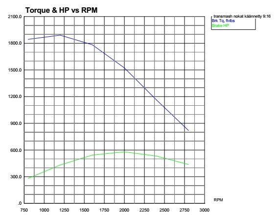
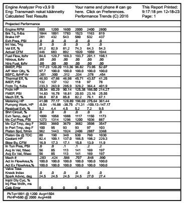
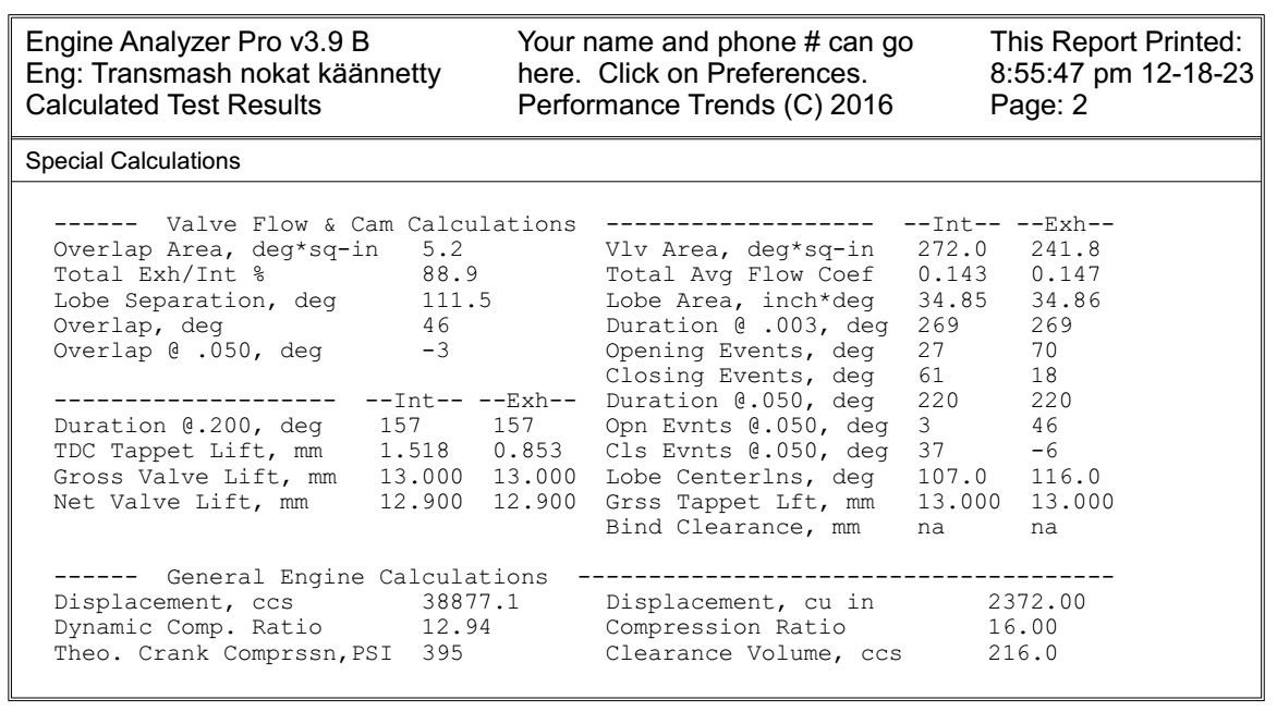
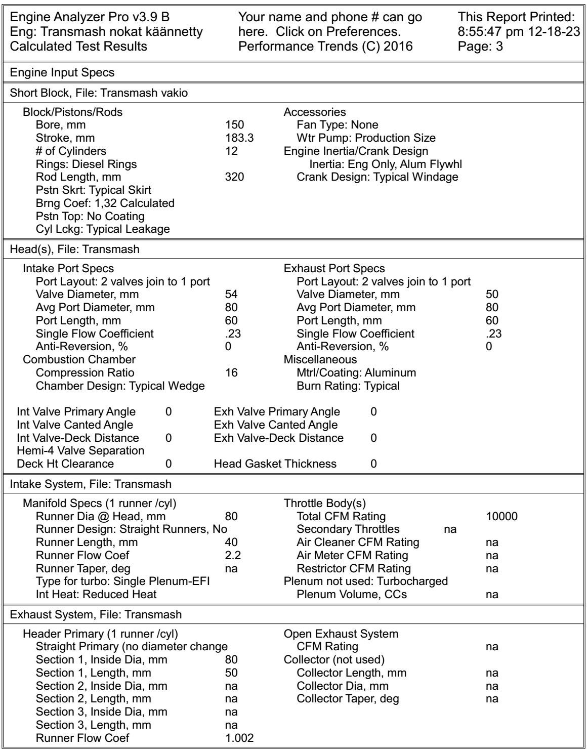
I have run engine in Engine analyzer pro software. Results looks pretty impressive but we have to keep mind that this is just simulation. It could be accurate if input information is absolute right. Dynograph and data below is simulated stock Transmash engine, it should make 580hp at 2000rpm. Head flow is set in program so it give right power figure. Our starting point is pretty close to truth. Engine is natural aspirated stock if someone doesn't know.
Lets give it some boost and put pair of big garrets braethe some air. Dyno and data below is twin turbo Transmash based on turbos that maps I find from program. There is no intercooler like I will drive first summer. It should make over 1700hp but IAT are so high that it could broke. AFR is set lean, 18:1 so it should not make smoke.
What you think guys? BSFC is pretty impressive, power also. This boat should be fast and economical 47 feet performance boat. By the way my injection pump is set so 2400rpm have max quantity and 2500rpm it is on idle quantity. This setup fit well to engine mechanical features.
12-19-2023 | 01:41 PM
#275
Thread Starter
Registered
Joined: Jan 2010
Posts: 346
Likes: 874
From: Finland
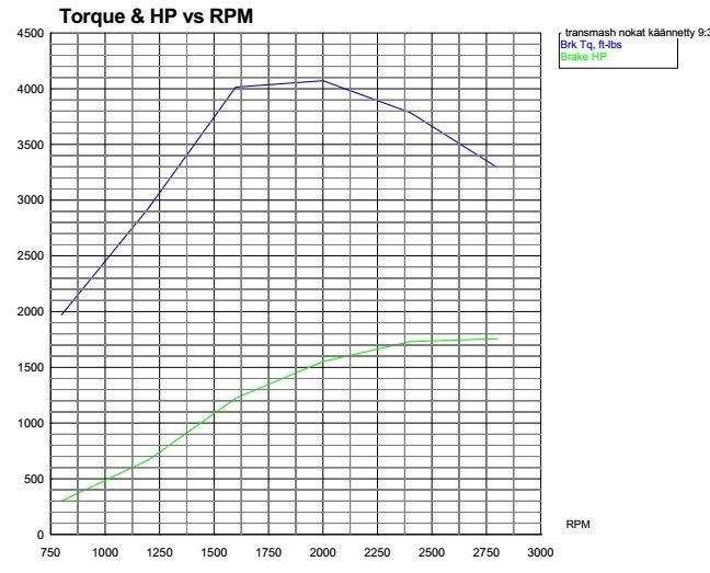
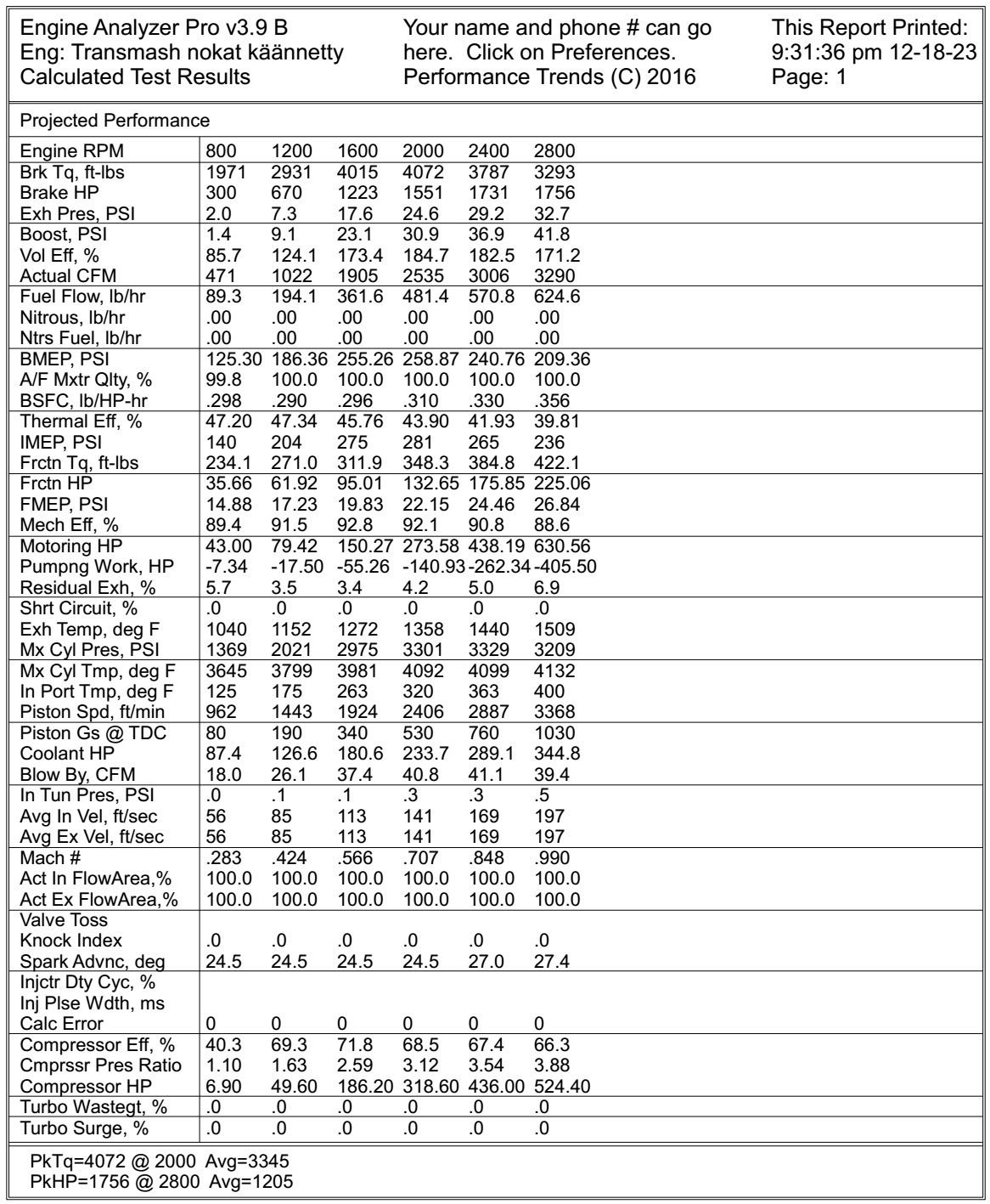
This is twin turbo intercooler simulation with more fuel, 15:1 AFR. I think we all are curious of this data It make 3365hp power, stock heads, stock everything but cam timing. Head flow is very poor, it can be ported pretty easy to make better cylinder filling without so much boost. I have seen over 4000hp results from program when modifying head flow. If someday I take huge power out from this engine, turbos will be hardest thing to get work. They will not spool in cruise rpm if they can move so much air at max power. Sequential quad turbo setup is only way to go then, but I don't think no driveline component can handle well over 10.000Nm torques....


It make 3365hp power, stock heads, stock everything but cam timing. Head flow is very poor, it can be ported pretty easy to make better cylinder filling without so much boost. I have seen over 4000hp results from program when modifying head flow. If someday I take huge power out from this engine, turbos will be hardest thing to get work. They will not spool in cruise rpm if they can move so much air at max power. Sequential quad turbo setup is only way to go then, but I don't think no driveline component can handle well over 10.000Nm torques....
12-27-2023 | 02:05 PM
#276
Thread Starter
Registered
Joined: Jan 2010
Posts: 346
Likes: 874
From: Finland
Today I made special heat exchanger. I found 54mm and 64mm copper tube and brass R1/4 and 1/2 fittings from local plumbing shop, they convert to three stage oil cooler.
700mm inner tube is one piece so it can't leak oil to water or otherwise, outer tube is made from three section and solder with phosphorus copper. Tube ends are made same way in hydraulic press like exhaust pipes.
I twisted 2.4mm TIG stick to spiral so it make fluid rotate around inner tube, it should increase efficiency. This special cooler make plumbing easier because it need only one cooler to cool three different oils, transmission/hydraulic fluid, steering fluid and split box fluid. I can't calculate how much cooling all systems need but this is good point to start.
At first I try find factory made coolers but this one was so easy to make that no ready cooler make sense and price of supplies was about 100€.
Cooler looks ugly but outlook doesn't affect to performance Maybe I have to clean flux off and paint it.


Test piece

test piece
700mm inner tube is one piece so it can't leak oil to water or otherwise, outer tube is made from three section and solder with phosphorus copper. Tube ends are made same way in hydraulic press like exhaust pipes.
I twisted 2.4mm TIG stick to spiral so it make fluid rotate around inner tube, it should increase efficiency. This special cooler make plumbing easier because it need only one cooler to cool three different oils, transmission/hydraulic fluid, steering fluid and split box fluid. I can't calculate how much cooling all systems need but this is good point to start.
At first I try find factory made coolers but this one was so easy to make that no ready cooler make sense and price of supplies was about 100€.
Cooler looks ugly but outlook doesn't affect to performance
Maybe I have to clean flux off and paint it.Test piece
test piece
12-27-2023 | 03:06 PM
#277
Offshoreonly Advertiser
Joined: Mar 2001
Posts: 2,518
Likes: 283
From: Pompano Beach FL, USA
I really don't mind bad if someone try help me, I appreciate that! Actually this thread is made for getting some information, tips and good debate technical things.
I have think about stainless fatigue and if there constant pressure against flap, they should be fine. Gasoline V8 with headers make so high speed pulses towards flaps that forces may be multiplied versus constant pressure. Diesel V12, constant pressure exhaust manifolds whom displacement is huge and turbocharger after that kill almoust all pulses. I had 29 baja with twin tuned 525's before, exhaust pulses are very strong! Exhaust valve opening time and ramp affect it also. This V12 engine idle without turbos a month ago and there come almost steady exhaust stream.
I made mistake to flaps CAD drawing, outer screw holes are too close to center. I need to put extra screws near shaft bearing so shaft won't flex so much.
No flattening shafts would be much better but somekind press jig have to be manufacture for flaps?

Yes I agree the exhaust should be pretty smooth. My mufflers were on 6000 RPM V8 with Y pipes.
Figuring out the exact shape of the disc needed to come out round after the bending was above my pay grade. I just made some oversized blanks, did the bending and cut to size after.
I attached a drawing (best I could from memory) of the fixture I used to bend them. The rods are same as shaft diameter and welded to a couple of pieces of plate. Bottom 2 are far enough apart to allow for the thickness of the flap plus a little extra.
__________________
Marc
www.mercruiserparts.com
www.go-fast.com
www.bammarine.com
www.cyborgtransmissions.com
It's not alive -www.BoatStuffExpress.com - temporarily retired
Marc
www.mercruiserparts.com
www.go-fast.com
www.bammarine.com
www.cyborgtransmissions.com
It's not alive -www.BoatStuffExpress.com - temporarily retired
01-10-2024 | 01:38 PM
#278
Thread Starter
Registered
Joined: Jan 2010
Posts: 346
Likes: 874
From: Finland
A lot of things have happened after last update. Let's start of complete engine.


Exhaust, turbocharger and tail pipe supports and exhaust pressure control flaps are ready. 5" tailpipes are 5 feet distance each others, it looks weird because engine is so big.
I try take small segmet off upper half of flaps so exhaust pressure make force to open flaps. Small pneumatic cylinder act against that force to keep constant exhaust pressure at idle. piston side of cylinder can open flaps when gear is engaged or driver just want open flaps. Tails are dry to tip.

Three stage copper heat exchanger find own place near other exchangers so raw water piping would be as easy as it could be.


Hydraulic driven 2.25" jabsco raw water pump is also ready. It caused head scratching to make it as short as possible. I found out if spline sleeve is located inside outer bearing, it makes complete package 2" shorter. More lathe time but it was worth of it. I won't mount pump to engine but to the outside of stringer. It will be part of boat, not engine. Hydraulics will get quick connectors so I can remove hoses without oil catastrof in bilge and short circuit pump out of use when engine is tested dry. I get pump for free, it was total junk, brass housing was only usefull part without repair welding, grinding etc..
Crankcase vacuum pump make too much heat in test run, it warmed up to 100C. It's huge carbon blade air motor that I use pulling vacuum, but blade have so much friction to housing and temperature goes up. Solution was 4mm inner diameter hose from dry sump oil tank to pump vacuum fitting. Now it draw oil to lubricate and cool pump, oil goes back to tank with breather air. When I get barrel of straight SAE 50 diesel oil, I make new test run for all new parts, hope it will be success.
Exhaust, turbocharger and tail pipe supports and exhaust pressure control flaps are ready. 5" tailpipes are 5 feet distance each others, it looks weird because engine is so big.
I try take small segmet off upper half of flaps so exhaust pressure make force to open flaps. Small pneumatic cylinder act against that force to keep constant exhaust pressure at idle. piston side of cylinder can open flaps when gear is engaged or driver just want open flaps. Tails are dry to tip.
Three stage copper heat exchanger find own place near other exchangers so raw water piping would be as easy as it could be.
Hydraulic driven 2.25" jabsco raw water pump is also ready. It caused head scratching to make it as short as possible. I found out if spline sleeve is located inside outer bearing, it makes complete package 2" shorter. More lathe time but it was worth of it. I won't mount pump to engine but to the outside of stringer. It will be part of boat, not engine. Hydraulics will get quick connectors so I can remove hoses without oil catastrof in bilge and short circuit pump out of use when engine is tested dry. I get pump for free, it was total junk, brass housing was only usefull part without repair welding, grinding etc..
Crankcase vacuum pump make too much heat in test run, it warmed up to 100C. It's huge carbon blade air motor that I use pulling vacuum, but blade have so much friction to housing and temperature goes up. Solution was 4mm inner diameter hose from dry sump oil tank to pump vacuum fitting. Now it draw oil to lubricate and cool pump, oil goes back to tank with breather air. When I get barrel of straight SAE 50 diesel oil, I make new test run for all new parts, hope it will be success.
01-10-2024 | 02:08 PM
#279
Thread Starter
Registered
Joined: Jan 2010
Posts: 346
Likes: 874
From: Finland
More updates, steering cylinders are ready.

These are boat original cylinders that are shortened and modified to fit my drive system. Rod ends are 20mm stainless ones.It was very difficult to make short cylinders with maximum stroke.

Comparison of original and modified steering ram. I don't like clevis joints and they are way too long for this aplication. I hope ball rod end angle movement is enough.


Tube side end have is threaded and welded both sides. Original (Latham maybe?) cylinder desing was so long that I wouldn't never get geometry right. Now Tube end is as short as it can be.
Welding was time consuming because parts had to be cooled down many times in water and get dry before welding can continue but all goes well.

Piston fastening and rod end is shorted also as short as possible. Piston get M18x1.5 thread inside unlike original thread after piston style fastening. Rods are now 25.0mm, originals was 1" (25.4mm), Seal company make fit into place sealings for me, metric rod and imperial housing.
Things go ahead pretty fast now. Today I visit new to me machine shop that make two splitbox shafts, inner splines to gears and carbon driveshafts end shafts. All those parts will be made of 34CrNiMo6 steel (1000N/mm2), let see is it good enough. Price made a choice, b�hler 720 (2000N/mm2) cost about 70€/kg and 34CrNiMo6 4€/kg
These are boat original cylinders that are shortened and modified to fit my drive system. Rod ends are 20mm stainless ones.It was very difficult to make short cylinders with maximum stroke.
Comparison of original and modified steering ram. I don't like clevis joints and they are way too long for this aplication. I hope ball rod end angle movement is enough.
Tube side end have is threaded and welded both sides. Original (Latham maybe?) cylinder desing was so long that I wouldn't never get geometry right. Now Tube end is as short as it can be.
Welding was time consuming because parts had to be cooled down many times in water and get dry before welding can continue but all goes well.
Piston fastening and rod end is shorted also as short as possible. Piston get M18x1.5 thread inside unlike original thread after piston style fastening. Rods are now 25.0mm, originals was 1" (25.4mm), Seal company make fit into place sealings for me, metric rod and imperial housing.
Things go ahead pretty fast now. Today I visit new to me machine shop that make two splitbox shafts, inner splines to gears and carbon driveshafts end shafts. All those parts will be made of 34CrNiMo6 steel (1000N/mm2), let see is it good enough. Price made a choice, b�hler 720 (2000N/mm2) cost about 70€/kg and 34CrNiMo6 4€/kg


