

MAG Cam degreed doesn't match what's posted
 03-10-2021 | 11:41 AM
#1
Thread Starter
Registered
Joined: Jan 2017
Posts: 315
Likes: 88
From: SE Virginia/NH
Hey guys,
I degreed my new/used 454 MAG cam (431-850478) and it's off 8 degrees for both the ICL and the ECL. Have any of you actually degreed one and can confirm some numbers for me? What I found posted out here was the following:
224*/224* @ .050" duration
.483"/.483" lift
115.5* LSA
109* ICL
122* ECL
My cam degreed at the following:
229.5*/231.5*
.481"/.484"
115.5 LSA
117* ICL
114* ECL
Thanks for any help.
edit:
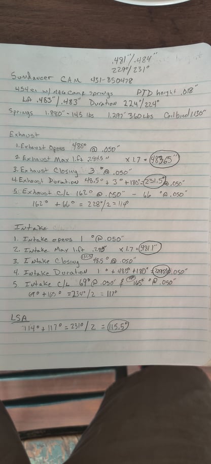
Here are my notes... and method if anyone sees a flaw in my calcs.
3. Zero the degree wheel. Use the shortest
pointer possible.
4. Install Lobe Lift tool with dial indicator and
zero. #1 exhaust is the first lobe on the cam and on the driver's side.
5. Turn crank clockwise until on the base circle of lobe. Zero dial indicator.
6. 1st Reading. Exhaust Opening:
a. Exhaust Opening @ .050 (lifter should be
on base circle.)
b. Rotate engine clockwise.
c. Stop when the dial indicator reaches .050".
d. Look at the degree wheel. Write down the number.
e. Compare this number to the Cam Card
Exhaust Opens.
7. 2nd Reading. Exhaust Max Lift:
Note: The dial indicator should be at .050" from the previous reading. It moved .050" from the base which means if you add another .050" it will equal one complete revolution or .100" on the dial indicator.
a. Rotate the crank clockwise.
b. Watch the dial indicator. The needle will stop and begin to go counter clockwise. In between that spot, take your reading and write it down. This is your lift. ie. .3675"
c. Multiply the lift from step 7b by your Rocker Arm Ratio. ie. .3675" x 1.7=.62475" . This is Max Exhaust Lift.
8. 3rd Reading. Exhaust Closing @ .050"
a. Rotate the crank clockwise.
b. The dial indicator needle will start to turn counter clockwise as the exhaust is closing. Keep track of the number of revolutions.
c. Stop when you get to .050" before the base.
If you pass it, go back further than .050" and
come back to .050".
d. Look at the degree wheel and write down
the number.
e. Compare this number to the Cam Card
Exhaust Closes.
9. 4th Reading. Duration @ .050".
a. Add your 1st and 3rd readings plus 180. (Ex. Opens + Ex. Closes +180= Duration @ .050")
10. 5th Reading. Lobe Center Line of exhaust lobe.
a. Two readings are being taken. One reading on each side of the lobe at Max Lift measuring down .050".
b. Rotate the engine so the lifter is on the base circle. Zero the dial indicator.
c. Rotate the engine so the lifter is at max lift. Zero out the dial indicator.
d. Rotate the engine Counter Clockwise one full dial indicator revolution or .100" to remove
timing chain slack.
e. Rotate the engine Clockwise to .050". Look at the degree wheel and write down the number.
f. Rotate the engine Clockwise to max lift.
g. Rotate the engine Clockwise until the dial indicator reads .050". Look at the degree wheel and write down the number.
h. Add the two numbers together from step 10
e and step 10 g. Divide answer by 2=Center Line of Exhaust Lobe.
Intake readings: Remove the Lobe Lift Tool and dial indicator and move them to the Intake Lobe. Repeat steps 5-10 for Intake.
Lobe Separation Angle: Once you have both the Exhaust and Intake readings, compute the Lobe Separation Angle.
a. (Center Line Exhaust + Center Line Intake)/
2=Lobe Separation Angle.
I degreed my new/used 454 MAG cam (431-850478) and it's off 8 degrees for both the ICL and the ECL. Have any of you actually degreed one and can confirm some numbers for me? What I found posted out here was the following:
224*/224* @ .050" duration
.483"/.483" lift
115.5* LSA
109* ICL
122* ECL
My cam degreed at the following:
229.5*/231.5*
.481"/.484"
115.5 LSA
117* ICL
114* ECL
Thanks for any help.
edit:
Here are my notes... and method if anyone sees a flaw in my calcs.
3. Zero the degree wheel. Use the shortest
pointer possible.
4. Install Lobe Lift tool with dial indicator and
zero. #1 exhaust is the first lobe on the cam and on the driver's side.
5. Turn crank clockwise until on the base circle of lobe. Zero dial indicator.
6. 1st Reading. Exhaust Opening:
a. Exhaust Opening @ .050 (lifter should be
on base circle.)
b. Rotate engine clockwise.
c. Stop when the dial indicator reaches .050".
d. Look at the degree wheel. Write down the number.
e. Compare this number to the Cam Card
Exhaust Opens.
7. 2nd Reading. Exhaust Max Lift:
Note: The dial indicator should be at .050" from the previous reading. It moved .050" from the base which means if you add another .050" it will equal one complete revolution or .100" on the dial indicator.
a. Rotate the crank clockwise.
b. Watch the dial indicator. The needle will stop and begin to go counter clockwise. In between that spot, take your reading and write it down. This is your lift. ie. .3675"
c. Multiply the lift from step 7b by your Rocker Arm Ratio. ie. .3675" x 1.7=.62475" . This is Max Exhaust Lift.
8. 3rd Reading. Exhaust Closing @ .050"
a. Rotate the crank clockwise.
b. The dial indicator needle will start to turn counter clockwise as the exhaust is closing. Keep track of the number of revolutions.
c. Stop when you get to .050" before the base.
If you pass it, go back further than .050" and
come back to .050".
d. Look at the degree wheel and write down
the number.
e. Compare this number to the Cam Card
Exhaust Closes.
9. 4th Reading. Duration @ .050".
a. Add your 1st and 3rd readings plus 180. (Ex. Opens + Ex. Closes +180= Duration @ .050")
10. 5th Reading. Lobe Center Line of exhaust lobe.
a. Two readings are being taken. One reading on each side of the lobe at Max Lift measuring down .050".
b. Rotate the engine so the lifter is on the base circle. Zero the dial indicator.
c. Rotate the engine so the lifter is at max lift. Zero out the dial indicator.
d. Rotate the engine Counter Clockwise one full dial indicator revolution or .100" to remove
timing chain slack.
e. Rotate the engine Clockwise to .050". Look at the degree wheel and write down the number.
f. Rotate the engine Clockwise to max lift.
g. Rotate the engine Clockwise until the dial indicator reads .050". Look at the degree wheel and write down the number.
h. Add the two numbers together from step 10
e and step 10 g. Divide answer by 2=Center Line of Exhaust Lobe.
Intake readings: Remove the Lobe Lift Tool and dial indicator and move them to the Intake Lobe. Repeat steps 5-10 for Intake.
Lobe Separation Angle: Once you have both the Exhaust and Intake readings, compute the Lobe Separation Angle.
a. (Center Line Exhaust + Center Line Intake)/
2=Lobe Separation Angle.
Last edited by HawkX66; 03-10-2021 at 01:06 PM.
 03-10-2021 | 09:48 PM
#4
Registered

Joined: Nov 2004
Posts: 14,154
Likes: 3,714
From: On A Dirt Floor
Just quoting myself from some other thread to have all the 454/502 mag mpi cams info put here
Go to Bam's site www.mercruiserparts.com , go to engine look up tables, find your engine and it's camshaft part # and then look below. Disclaimer: these are my notes from other sources and being human I am wrong sometimes.
Mag BBC 454/502 Flat Tappet (rect heads)
.004� 296*, 296*
.006� 286*, 286*
.050� 224*, 224*
.200� 130*, 130*
Valve lift with 1.7 .510�, .510�
LSA 115.5
Merc Part#431-9830 / GM#14096209
ICL 114 ATDC
ECL 117 BTDC
GM Part#10185060 (same as above but ground with 5 degrees advance)
ICL 109 ATDC
ECL 122 BTDC
======================================
Merc Mag Roller
Merc# 431-850478 / GM#12551622
.004 300*/ 300*
.006 288*/288*
.050� 225*/225*
.200� 125*/125*
Lift .483�/. 483�
ICL 109* ATDC ECL 122*BTDC
LSA 115.5*
Last edited by SB; 03-10-2021 at 09:51 PM.
03-10-2021 | 10:59 PM
#5
Platinum Member

Joined: Feb 2001
Posts: 4,303
Likes: 1,459
From: Virginia Beach
For anyone that needs this info, these are the full specs for the 1622 cam. Hoping there’s some
measurement/tool issues because I’m clueless as to
an issue.
We’re good and I have a backup cam if this one is really whacked for some reason.
GM / Mercruiser Part# 12551622
Duration
.004" 300/300
.006" 288/288
.050" 225/225
.200" 125/125
Lift .483"/.483"
ICL 109*
ECL 122*
LSA 115.5*
IVO -3* BTDC ( - indicates ATDC)
IVC 47* ABDC
EVO 48* BBDC
EVC -4* ATDC (- indicates BTDC)
Overlap -7*
Last edited by TomZ; 03-11-2021 at 07:35 AM. Reason: autocorrect
03-11-2021 | 06:12 AM
#6
Thread Starter
Registered
Joined: Jan 2017
Posts: 315
Likes: 88
From: SE Virginia/NH
Thanks for checking in SB. To answer your questions:
1. You're asking how I zeroed the degree wheel right? I set the piston at TDC and rotated the wheel until my pointer was pointing at zero and locked it down. To set TDC, I first rocked the piston fully in one direction, measured it, divided by two and rocked it in the other direction by that amount. I set my dial gauge up in the center of the piston with my bridge at that point. For the sake of taking any issue with that method out, I'll use a piston stop today to get zero. Even if I was off a little, which I don't believe I was, it wouldn't have been 8 degrees.
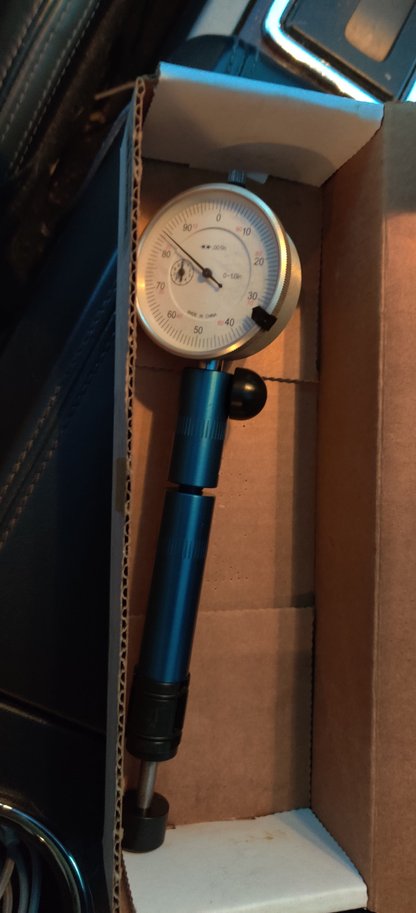
2. My lobe lift tool is the Proform one. I attached a pic. I don't have the squared off attachment and my machinist buddy said last night that it's possible the hemispherical head is causing an issue if the ramp is too steep. He lent me his tool that I'll try today.
This isn't my first engine. I've built a few before and degreed cams. For some reason this one has me stumped.


 03-11-2021 | 06:27 AM
#8
Thread Starter
Registered
Joined: Jan 2017
Posts: 315
Likes: 88
From: SE Virginia/NH
One more thing to add. I took the holder and extension out of the equation also and installed the dial indicator directly in the lobe tool. Here is a pic and also one of the tool my buddy lent me.

03-11-2021 | 06:42 AM
#10
Registered
Joined: Nov 2004
Posts: 14,154
Likes: 3,714
From: On A Dirt Floor
I use a positive piston stop too, with degree wheel, to find exact tdc too.
Does that round foot mimic exactly the the roller wheel diameter of your lifters ?
Does that round foot mimic exactly the the roller wheel diameter of your lifters ?
Last edited by SB; 03-11-2021 at 06:44 AM.

