


Dash Panel Material
 03-20-2024 | 12:11 PM
#51

Platinum Member


Joined: Feb 2001
Posts: 4,303
Likes: 1,459
From: Virginia Beach

One day I'm going the all digital route. My Livorsi gauges have held up well over the years but I'm sure they're on borrowed time - some are over ten years old for sure. I would need to do analog to digital converters for mine but figure I could do all of that under the helm.
Good thread!
Good thread!
 03-21-2024 | 07:16 AM
#52
Thread Starter
VIP Member


Joined: Jun 2021
Posts: 3,533
Likes: 2,142
From: SW Ohio
Image scaling and tracing
Brad, lay the panel on the ground and take a pic with your phone straight on as best you can then send it to you self via text to email.
Save the pic on your computer then import the image into CAD
Then you can trace over the image, after you get an outline done you can scale it to size to match the actual size of the piece. from there you can print it out full scale and lay the original panel on top to make sure it works and do any fine tuning you need to and from there you can play any way you want with layouts. Ive done this a few times for people
Brad, lay the panel on the ground and take a pic with your phone straight on as best you can then send it to you self via text to email.
Save the pic on your computer then import the image into CAD
Then you can trace over the image, after you get an outline done you can scale it to size to match the actual size of the piece. from there you can print it out full scale and lay the original panel on top to make sure it works and do any fine tuning you need to and from there you can play any way you want with layouts. Ive done this a few times for people
Yup. I've done quite a few graphics to DWG/DXF conversions myself. That's how I've been doing to hitch plugs in SolidWorks. But I've already dropped the panel off at the graphics shop. He's got a scanner that will capture the entire piece in one snapshot, align it and convert to DXF in minutes, plus he's gonna do a one-piece vinyl "wrap" that will include the stripe, a PQ graphic (the same one in the back window of my truck, scaled down), on a white CF hologram-like background. All I have to do is move the gauge holes around to suit my purpose.

I did manage to lose function in the engine hatch rocker switch during the process, but I lost it even before I got to it, as far as disconnecting and removal. Time to break out the multimeter and figure out why.
I also managed to pull the rocker cover off another rocker switch, and it's lost its mooring (broken), so it won't stay on. Suppose it could be glued on, or will it have to be replaced? It seems like the company (Carling) is still going strong. I might have to get a part number from them and order a new one. Already talked to the graphics shop about laser engraving the label on it (they have one) if I have to replace it.
Thanks. Brad.
Thanks. Brad.
03-21-2024 | 07:29 AM
#53
Thread Starter
VIP Member
Joined: Jun 2021
Posts: 3,533
Likes: 2,142
From: SW Ohio
I would do away with the gauges. Kept a few on my dash redo and never even look at them. Going digital is so much more precise and easier to read and if your motor is Vessel view capable it is even easier. They work now, but probably on borrowed time and then you'll never find a matching replacement. I'll probably redo mine at some point and remove the analog gauges.
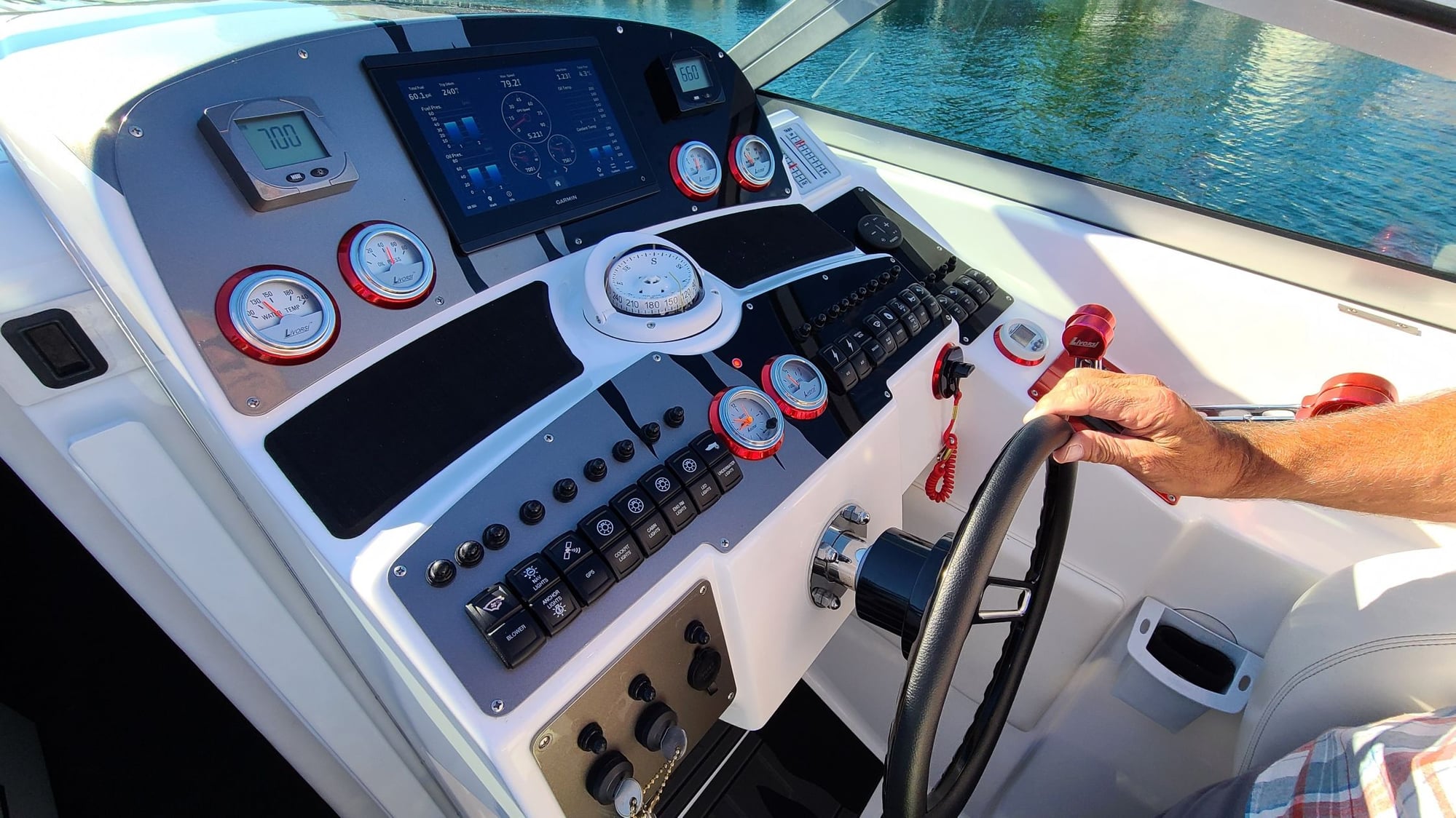
I hear you, and I don't dislike the digital route at all. The vessel-view aspect is very appealing. It's just too late in the game at this moment to go down that rabbit hole. Maybe in the future.
The gauge I ordered is a direct match to what I've already go, and they have all the others if something should come up. The GPS speedo is farqing expensive, though, comparatively. Time will tell if the build quality is still there on new gauges.
I'm even going to make a bezel for my Insta-Trim indicator gauge (it's a weird size that nobody makes a bezel for, and I am more than capable of the machining), and have it powder coated to match the bezels already installed. It bugs me that it's the oddball without one. Uniformity is important to me, which is the only reason I didn't jump on the option of the little volage indicator Dan brought up a while back. That would have made this whole process WAY easier. But no....

Thanks. Brad.
03-21-2024 | 01:59 PM
#54
Thread Starter
VIP Member
Joined: Jun 2021
Posts: 3,533
Likes: 2,142
From: SW Ohio
OK....
As mentioned, I lost function of the engine hatch rocker switch somewhere between the beginning of disassembly (I checked) and actually getting to disconnecting the terminals to the switch. Meaning the switch was working before work began, after work began, but stopped working at some point before I got to disconnecting the switch in question. Everything else seems to work fine. This tells me something else happened. I've cut a blue million zip ties, but I have a bundle of wires still bundled together, which includes the "to motor" wires from the switch.
The switch appears to be deisgned/wired a bit differently than the diagram I found on a search here on OSO:
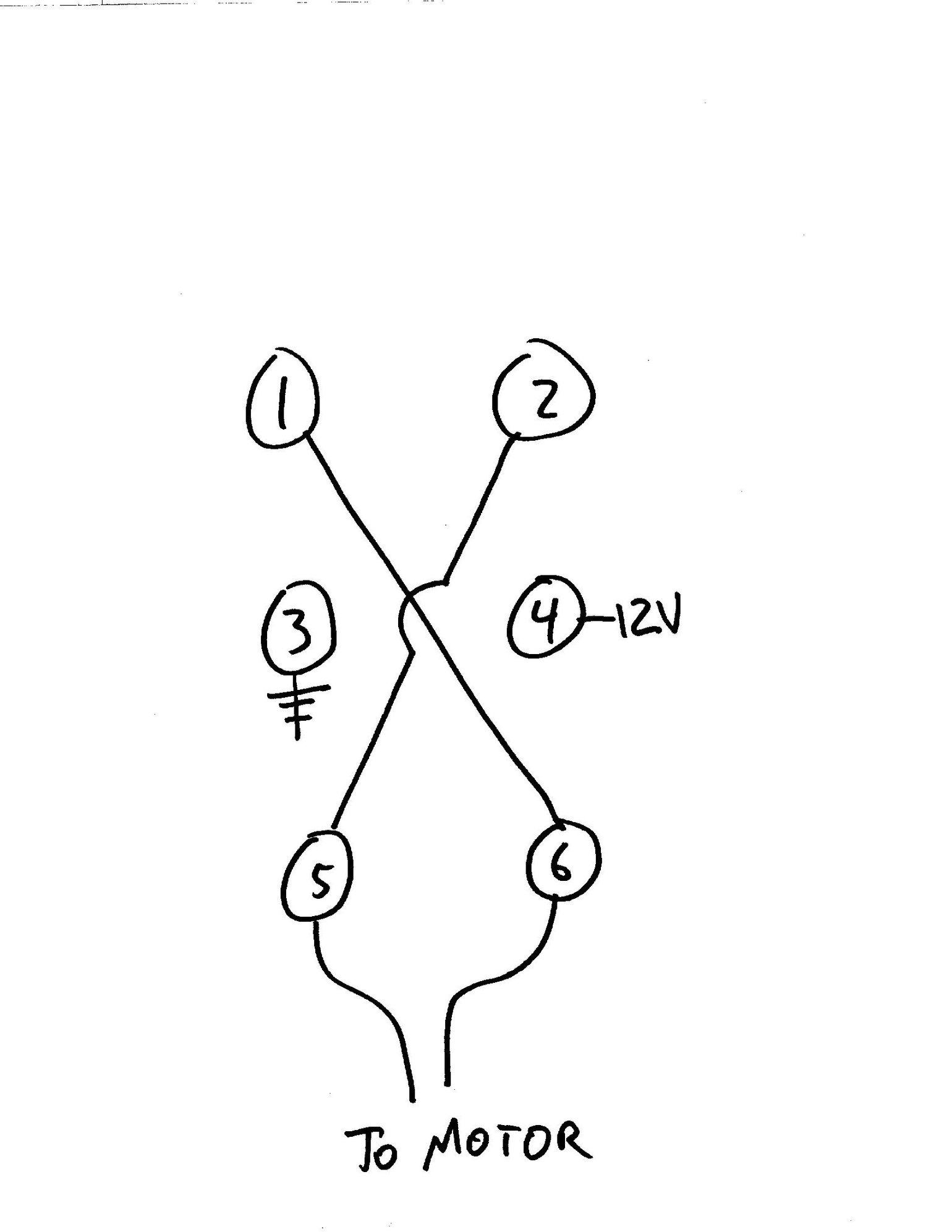
This is actually mirrored, as if looking at the terminals from the front of the switch, but it doesn't really matter. Using a multimeter, I find 13V from the wire leading to #4, and a solid ground between the wire terminal and the ground strap in the dash well. Testing between the ground strap and both output terminals on the switch, I get 13V when the switch is pressed in the appropriate direction. I have not checked at the motor, as that will require cutting the wires and reconnecting them, which I'm kinda loathe to do if it's not necessary.
Any ideas?
Thanks. Brad.
As mentioned, I lost function of the engine hatch rocker switch somewhere between the beginning of disassembly (I checked) and actually getting to disconnecting the terminals to the switch. Meaning the switch was working before work began, after work began, but stopped working at some point before I got to disconnecting the switch in question. Everything else seems to work fine. This tells me something else happened. I've cut a blue million zip ties, but I have a bundle of wires still bundled together, which includes the "to motor" wires from the switch.
The switch appears to be deisgned/wired a bit differently than the diagram I found on a search here on OSO:
This is actually mirrored, as if looking at the terminals from the front of the switch, but it doesn't really matter. Using a multimeter, I find 13V from the wire leading to #4, and a solid ground between the wire terminal and the ground strap in the dash well. Testing between the ground strap and both output terminals on the switch, I get 13V when the switch is pressed in the appropriate direction. I have not checked at the motor, as that will require cutting the wires and reconnecting them, which I'm kinda loathe to do if it's not necessary.
Any ideas?
Thanks. Brad.
Last edited by Brad Christy; 03-21-2024 at 02:03 PM.
03-21-2024 | 03:09 PM
#55

Were doomed!

Joined: Oct 2000
Posts: 7,100
Likes: 1,397
From: Chicago, IL
bypass the switch all together and just take the motor wires and put one to ground the other to power and see if the hatch ram works....if it clicks and nothing reverse them cause maybe you have it in the down setup. If that still doesn't work then you have to start digging in deeper...
__________________
-Wally
Money can't buy happiness, but it can buy horsepower. And I've never seen a sad person hauling a$$!
-Wally
Money can't buy happiness, but it can buy horsepower. And I've never seen a sad person hauling a$$!
03-21-2024 | 03:48 PM
#56
Thread Starter
VIP Member
Joined: Jun 2021
Posts: 3,533
Likes: 2,142
From: SW Ohio
bypass the switch all together and just take the motor wires and put one to ground the other to power and see if the hatch ram works....if it clicks and nothing reverse them cause maybe you have it in the down setup. If that still doesn't work then you have to start digging in deeper...
I found non-continuity in a "to motor" wire between the switch and a cluster connector; either #5 or #6 in my sketch. I unbundled it and started checking point to point at various points along the wire and found continuity from the bare wire inside the insulator of the blade connector and the other end of the wire, but not through the actual connector. Started separating the Y, and the blade connector came apart. The actual crimp contact had broken, but the jumper that Y'd them together was holding it in place. Pretty sure this was it. I'm betting I did it while wrestling around with the loomed wires trying to get the switches out.
As it happens, I don't have any blade connectors on hand at the moment, so I'm off to AutoZone momentarily to get some. News at eleven....
Thanks. Brad.
03-21-2024 | 05:09 PM
#58
Thread Starter
VIP Member
Joined: Jun 2021
Posts: 3,533
Likes: 2,142
From: SW Ohio
Guys,
On to the next question....
Where is the best place to tap into the oil flow for the sending unit? 496HO. It has a the ProCharger, but, otherwise, it's as Merc intended it: stock remote oil filter mount, stock oil cooler, etc.... Is there an easy, obvious tap somewhere that is plugged off in the absence of a sending unit? Or do I add one with fittings at a connection somewhere?
Thanks. Brad.
On to the next question....
Where is the best place to tap into the oil flow for the sending unit? 496HO. It has a the ProCharger, but, otherwise, it's as Merc intended it: stock remote oil filter mount, stock oil cooler, etc.... Is there an easy, obvious tap somewhere that is plugged off in the absence of a sending unit? Or do I add one with fittings at a connection somewhere?
Thanks. Brad.
03-21-2024 | 06:02 PM
#59
Registered

Joined: Sep 2014
Posts: 870
Likes: 259
From: Portland, OR
Guys,
On to the next question....
Where is the best place to tap into the oil flow for the sending unit? 496HO. It has a the ProCharger, but, otherwise, it's as Merc intended it: stock remote oil filter mount, stock oil cooler, etc.... Is there an easy, obvious tap somewhere that is plugged off in the absence of a sending unit? Or do I add one with fittings at a connection somewhere?
Thanks. Brad.
On to the next question....
Where is the best place to tap into the oil flow for the sending unit? 496HO. It has a the ProCharger, but, otherwise, it's as Merc intended it: stock remote oil filter mount, stock oil cooler, etc.... Is there an easy, obvious tap somewhere that is plugged off in the absence of a sending unit? Or do I add one with fittings at a connection somewhere?
Thanks. Brad.
Last edited by Diamond Dave; 03-21-2024 at 06:05 PM.
03-21-2024 | 06:19 PM
#60
Thread Starter
VIP Member
Joined: Jun 2021
Posts: 3,533
Likes: 2,142
From: SW Ohio
87MirageIntruder Has upgraded everything oil wise on his built/ Whippled 496.
Thanks for that. PM’d him.
Thanks. Brad.

