

Never again, probably !
 07-09-2021 | 07:10 PM
#121
Thread Starter
Registered

Joined: May 2009
Posts: 1,941
Likes: 526
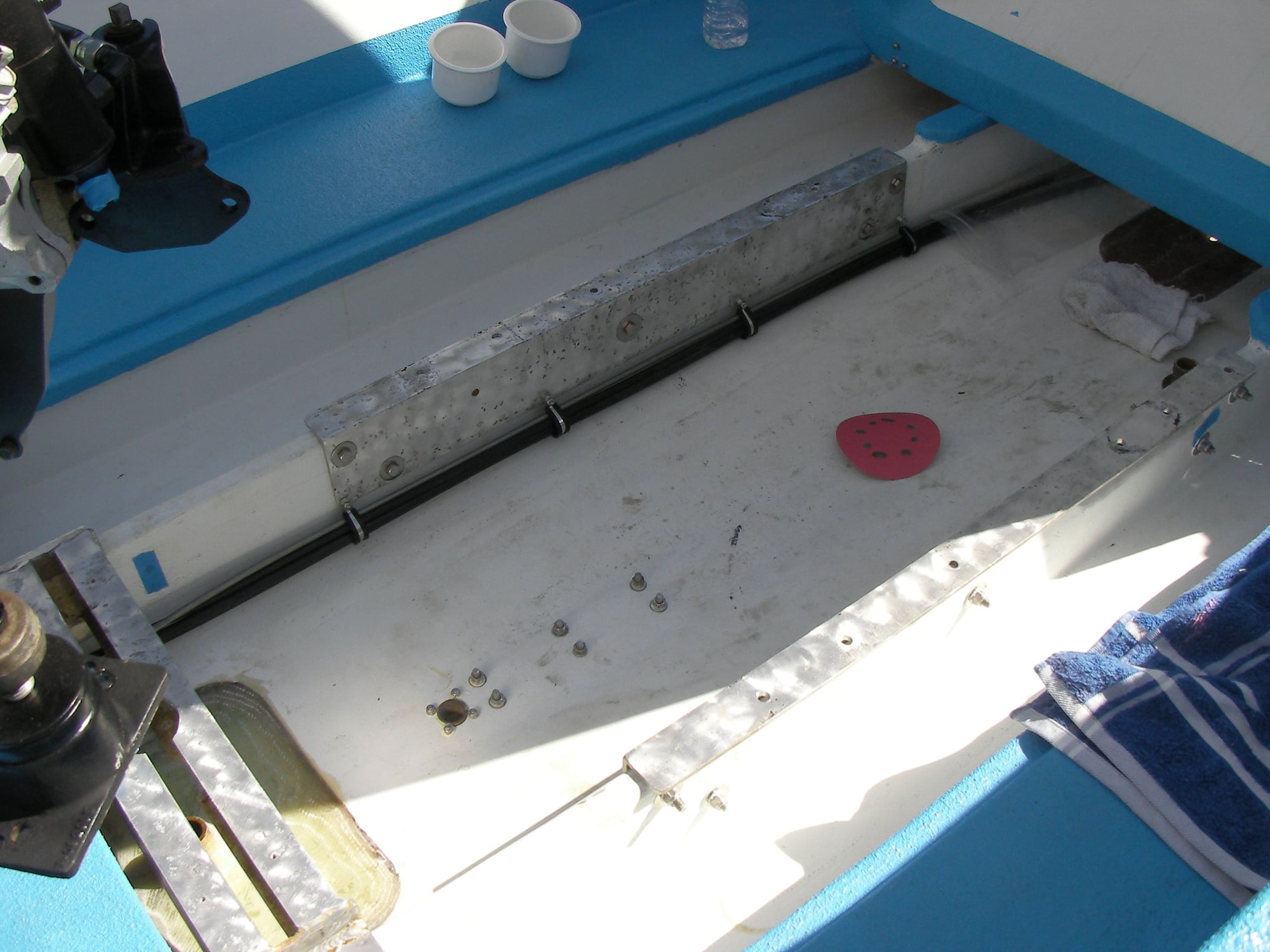
Calling the pad 4, the stringers are at 1 1/2
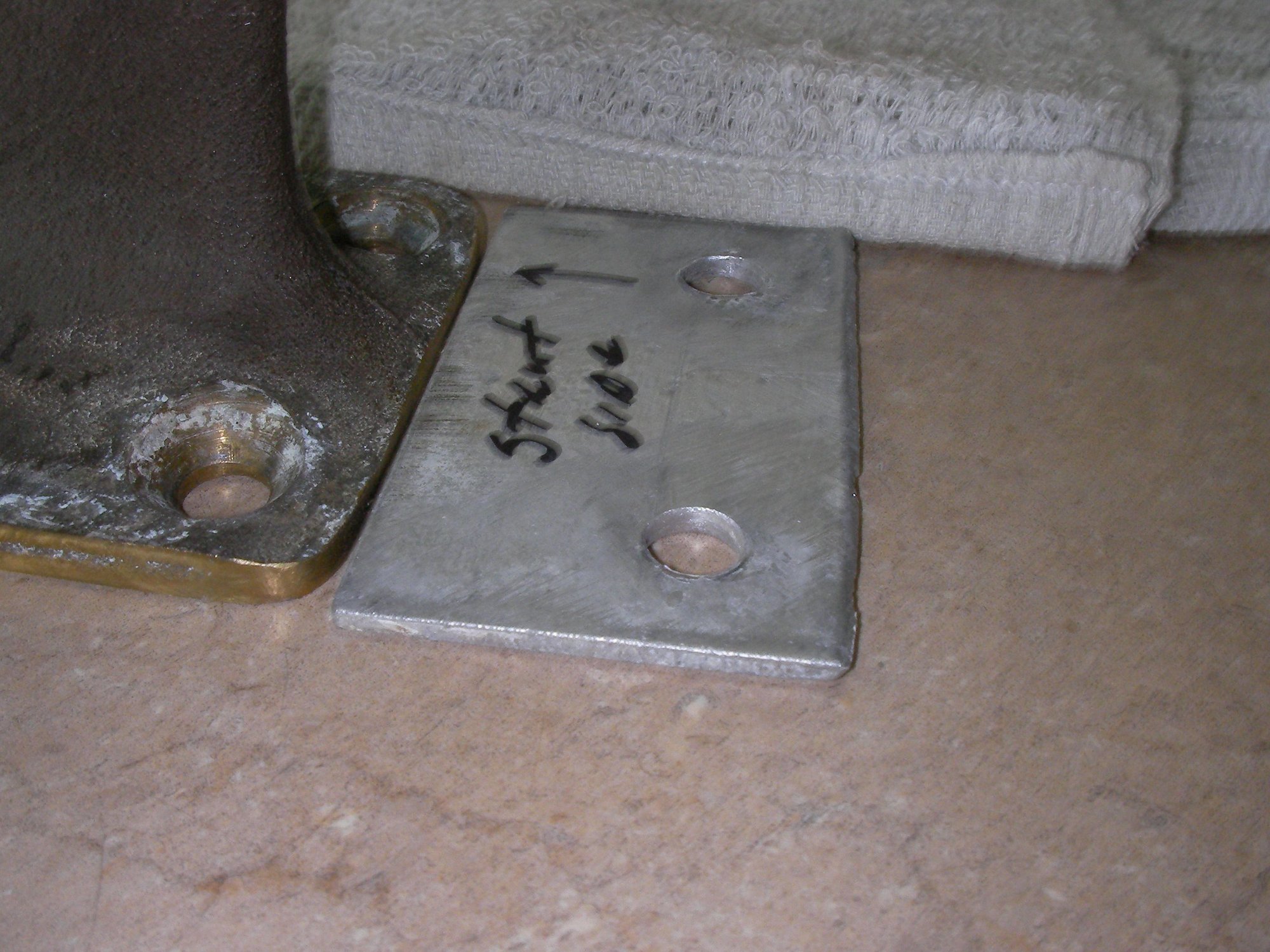
Calling the strut port 2 ( it was hacked at the factory) Strut port should be same as pad
take all the numbers pad port and stringers, rotate the pad to zero, strut port is neg 2 stringers are 5 1/2.
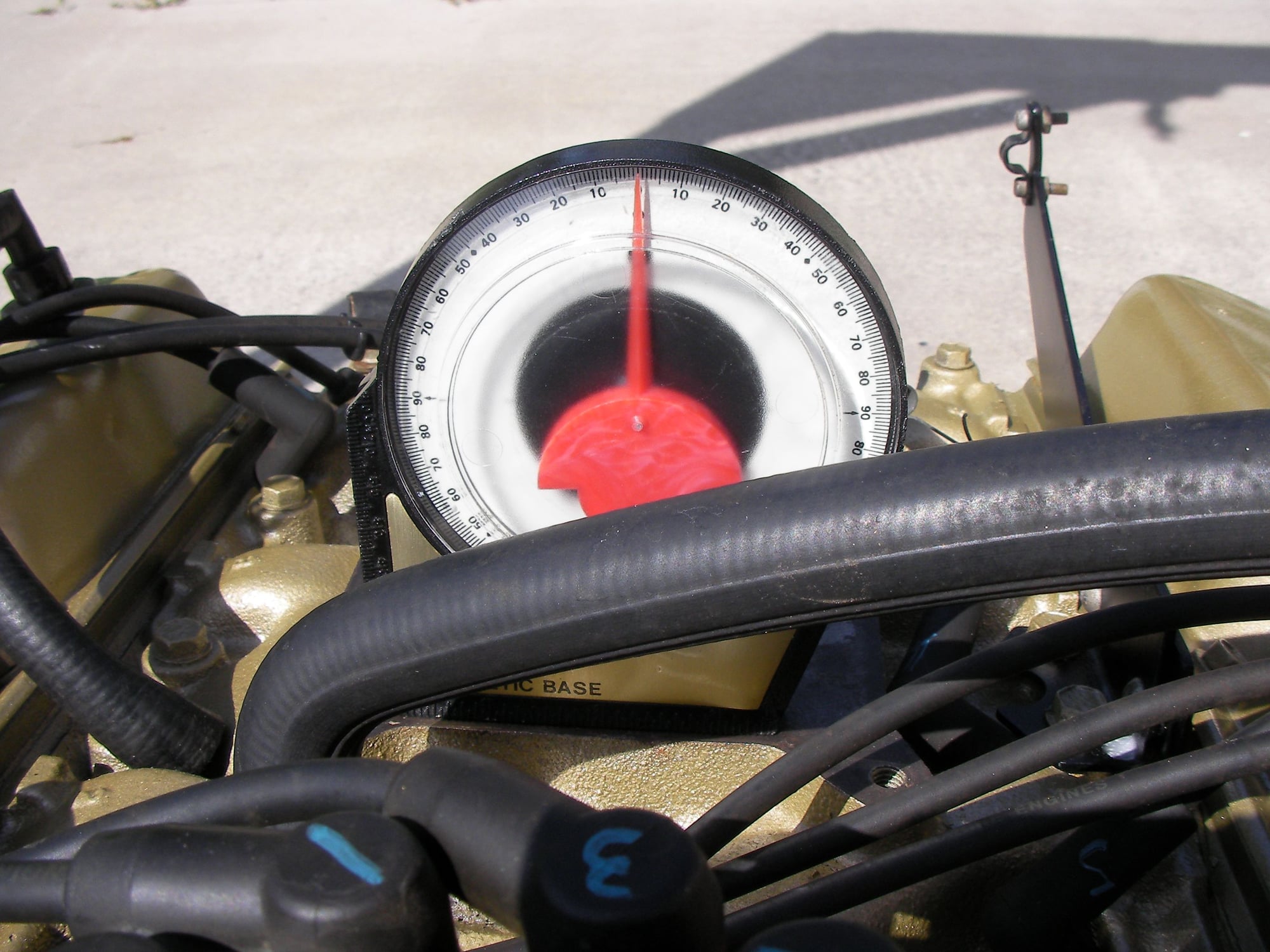
now get to the strut and shaft angles
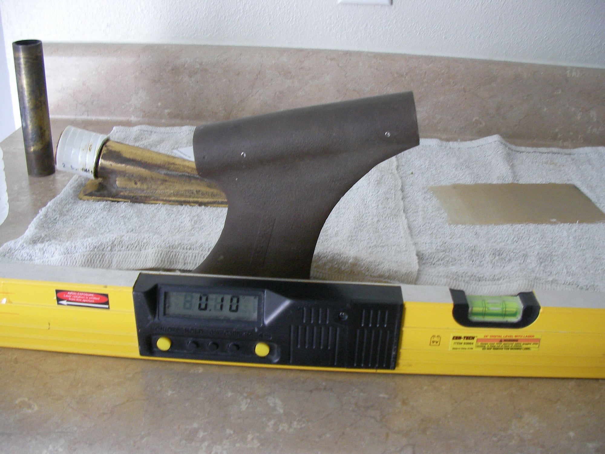
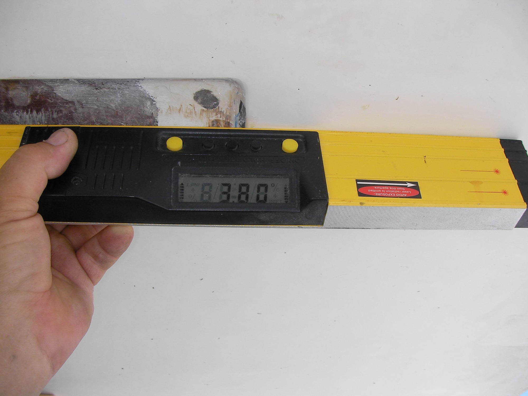
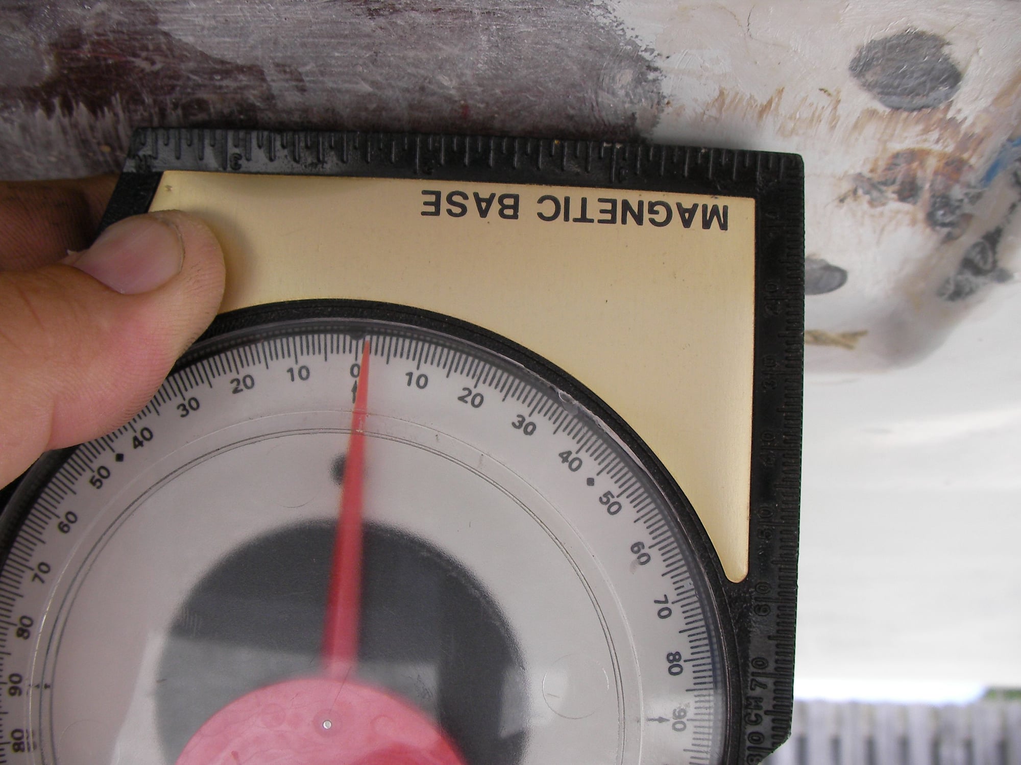
Calling that level
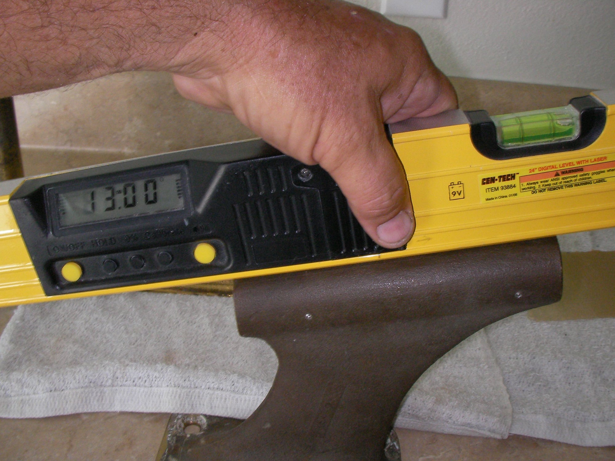
Strut is 13
Factory hack shim under rear of strut.
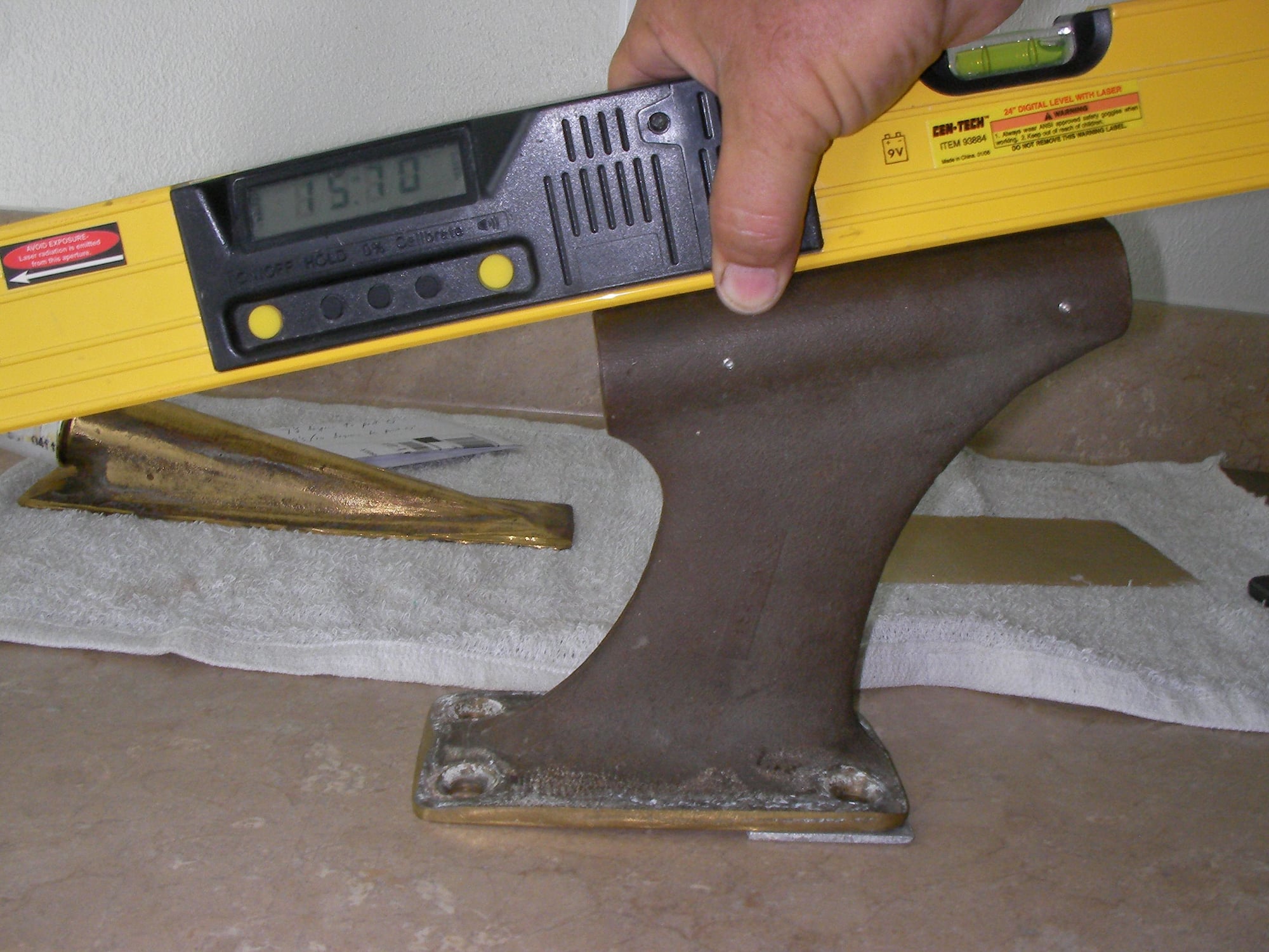
Calling that 16 with the shim in place, add the 2 from them grinding thats 18 degrees shaft angle. Thats like trimming your drive negative 5 degrees
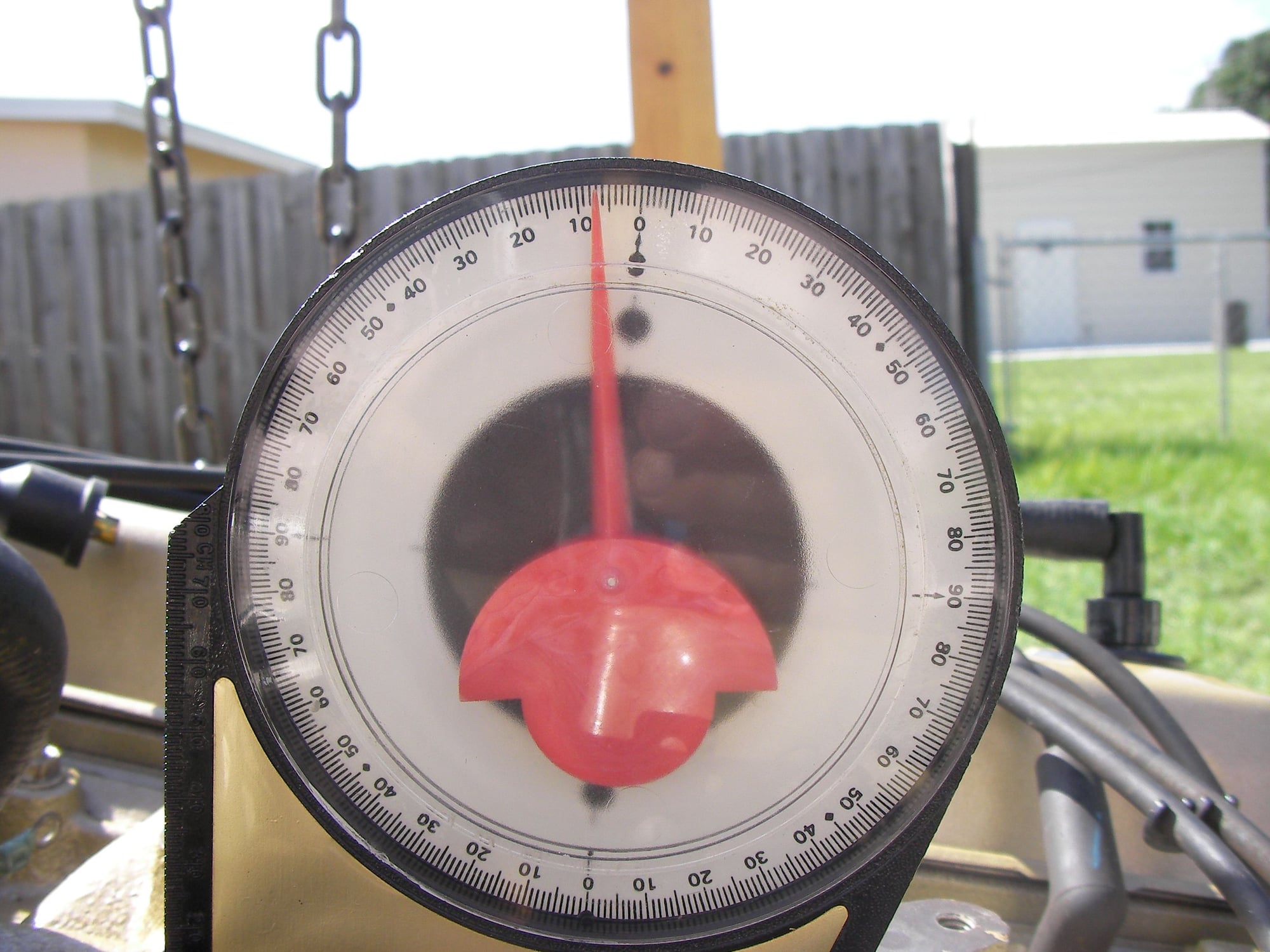
Engine at 7 1/2, stringers are at 5 1/2, should be 13 which is correct shaft angle
Side to side
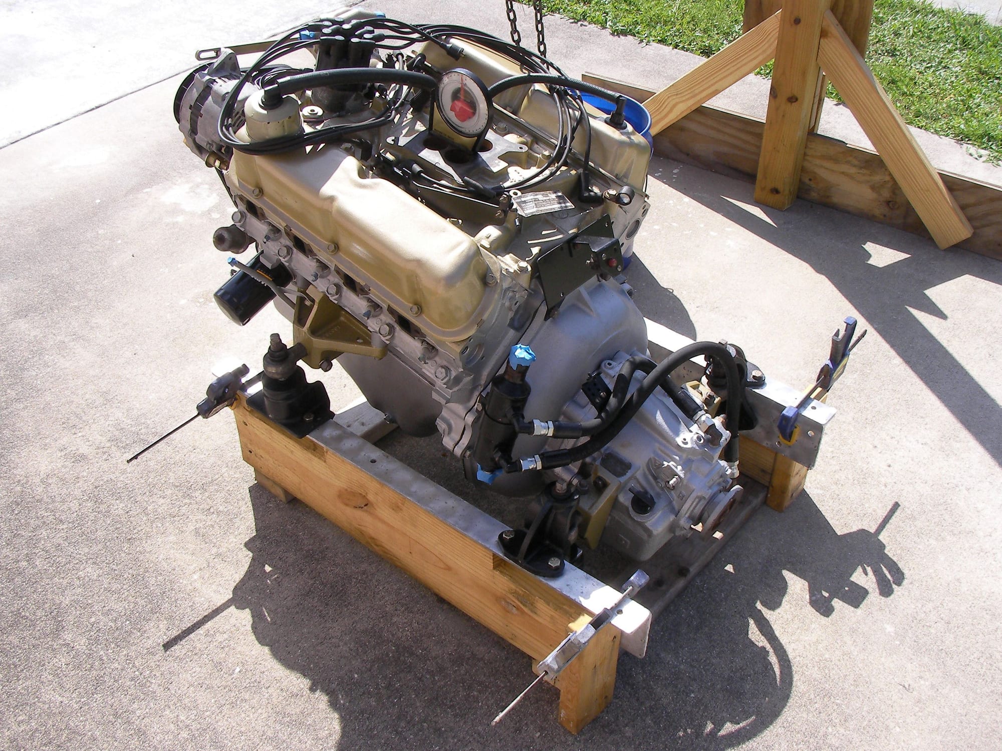
Engines on dummy stringers set close to width, center and angle. Should be in the ball park and set right in.
i'm going to start backwards, set in engine and find front/back for correct strut/prop spacing , about 1/2 inch (not the 2 inches the factory left)
With engine centered and at 13 degrees connect shaft to engine, slide on strut and find out how far the strut is away from it's port and how much of what it's gonna take to get it back to the 13 it's supposed to be with the engine-shaft-prop lined up down the keel, not slung way over to port like it was.
once whatever it takes to get the strut where its supposed to be i'll mount it and then do the alignment the regular way and then bed the stern tube.
Theres no way i'm just gonna slam it together.
 07-10-2021 | 02:25 PM
#122
Thread Starter
Registered
Joined: May 2009
Posts: 1,941
Likes: 526
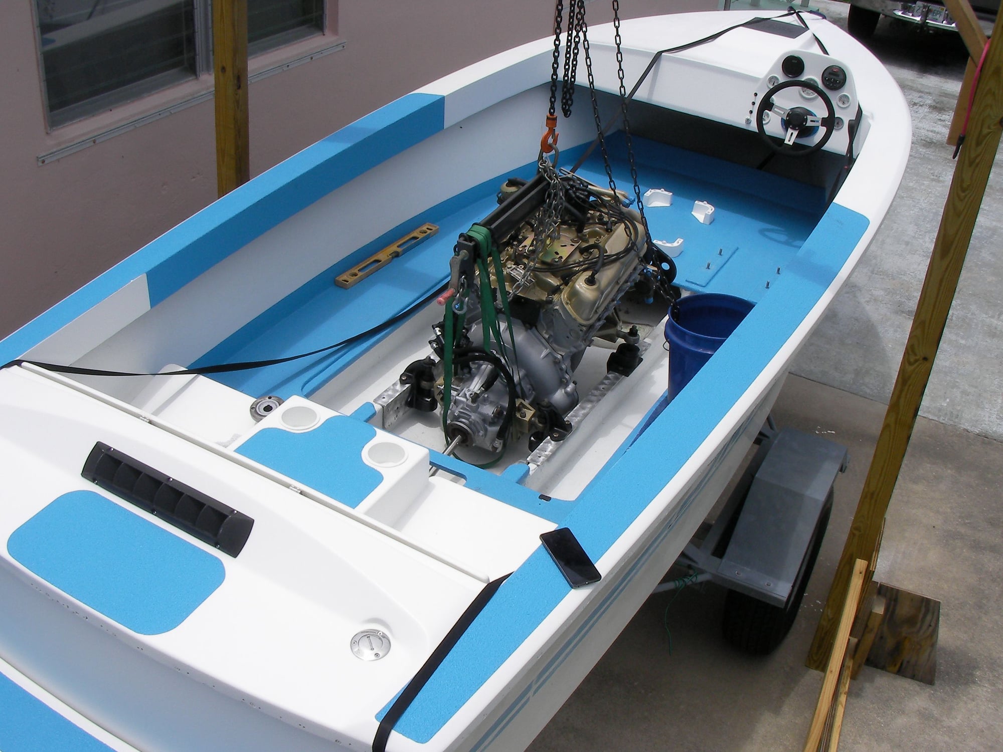

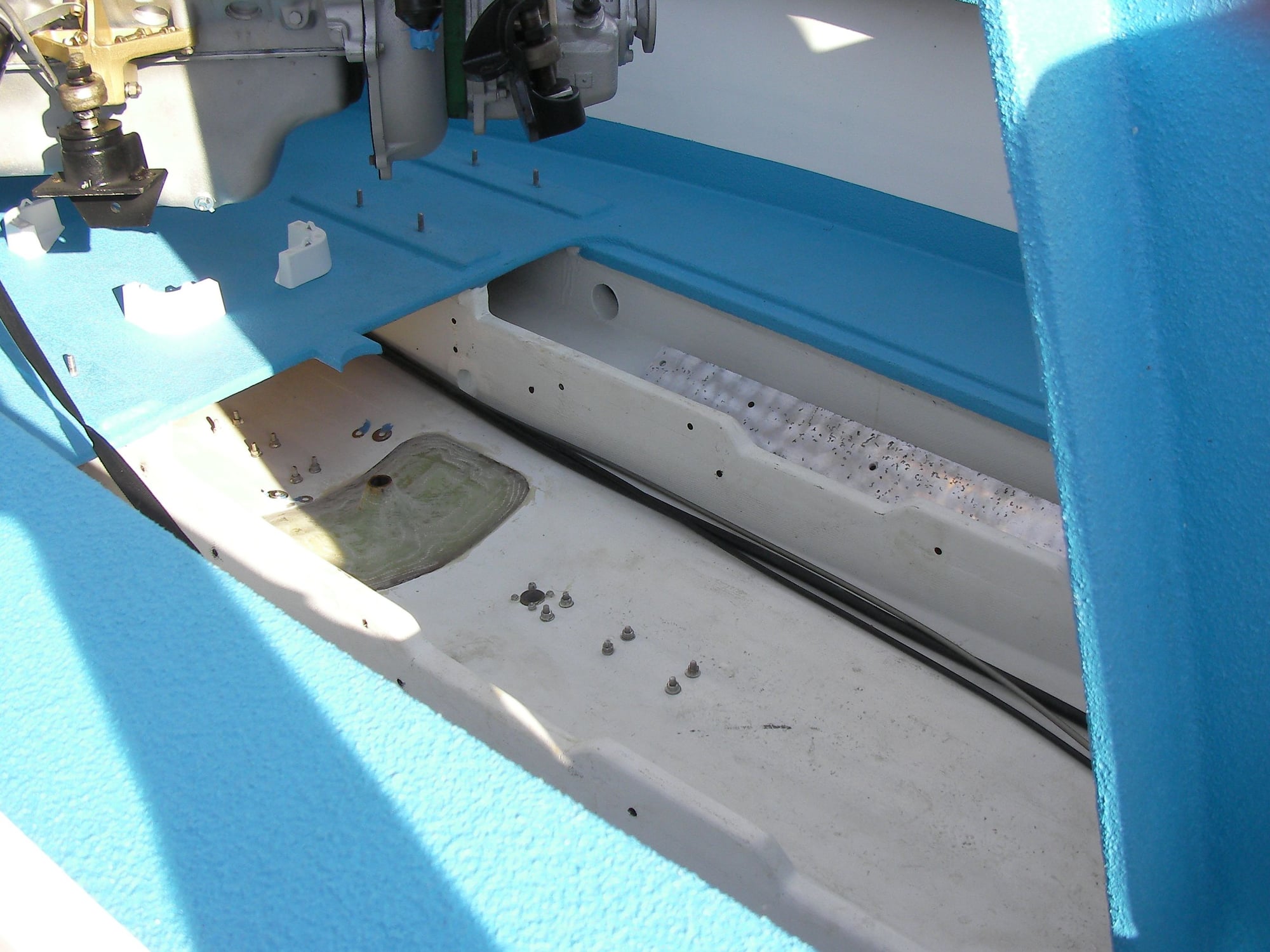
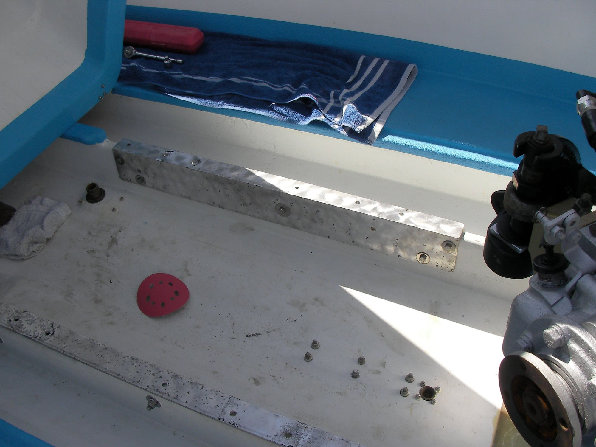
the engine landed 1/16 off center and 3/16 forward, third pic is after moving back 3/16.
drilled 1 bolt hole in each corner, plan is unbolt pedestals from angle, pull engine up a foot and drill remaining 6 bolt holes.
confident enough to let engine hang while they get epoxy soaked.
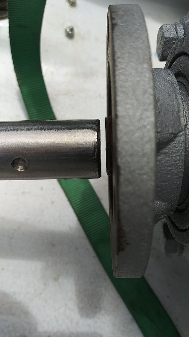
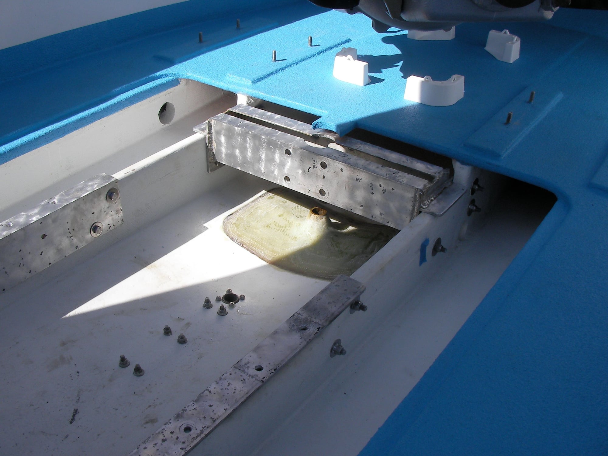
spent time grinding the shim to get 2 degrees back and when installed the shaft wouldn't go thru the hole !!!
The shaft won't go in unless that hunk of aluminum is in there, if the stern tube hole was moved forward about 2 inches it would work at 13 degees as designed. The stern tube hole is molded in, so It's either the mold the batch of parts or some other hackery at some point in it's life.
was gonna name it ski force 1 but now it might as well be eating crow
07-12-2021 | 04:01 PM
#123
Thread Starter
Registered
Joined: May 2009
Posts: 1,941
Likes: 526
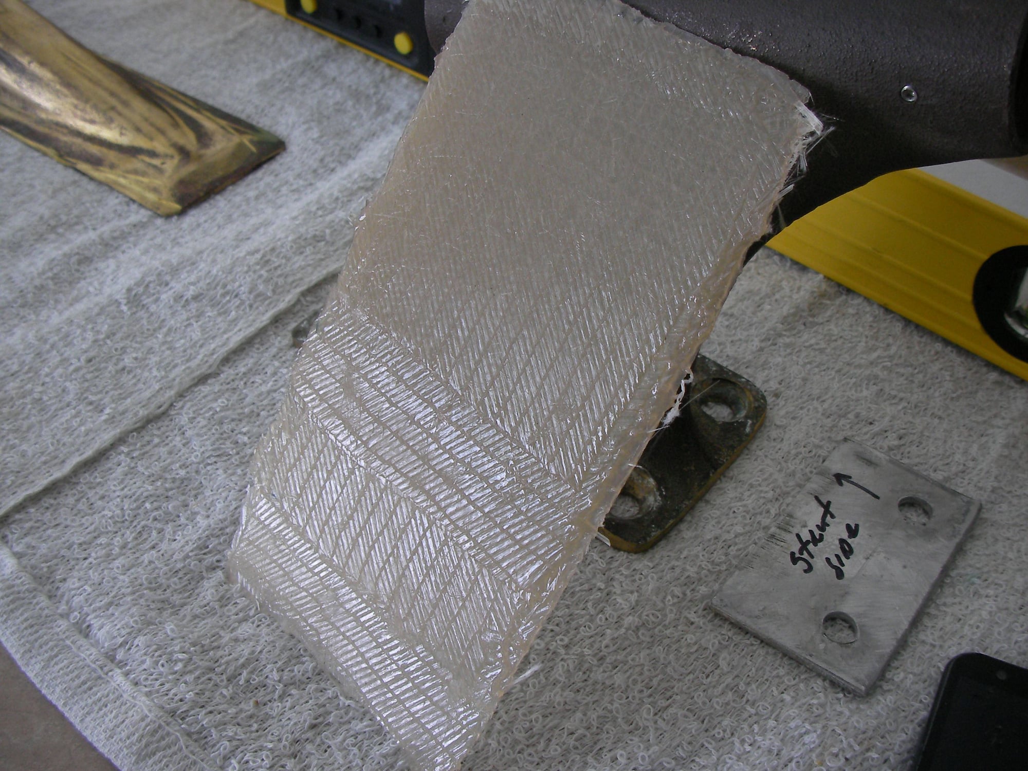
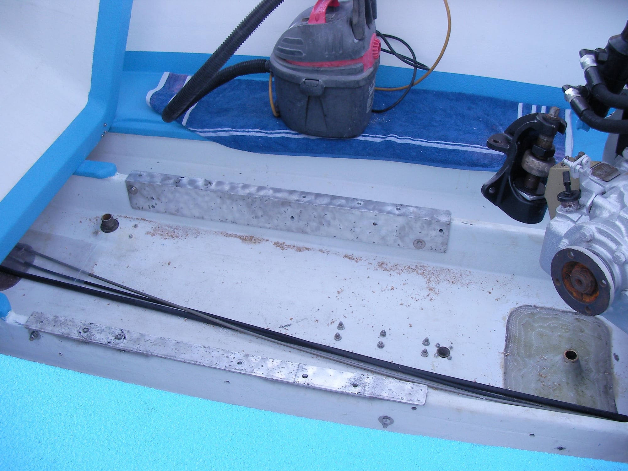
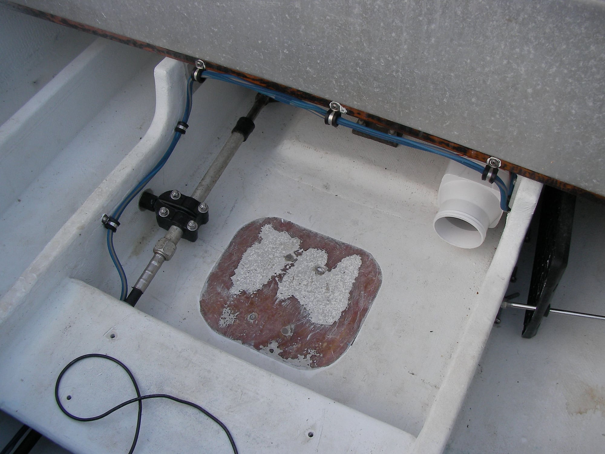
Engine angle to stringer holes drilled-epoxy soaked & 4200 on both sides of the stringers.
angles torqued, same for the ski pylon mount and the steering knuckle hole.
maybe waterproof, maybe not but piece of mind anyway.
angles torqued, same for the ski pylon mount and the steering knuckle hole.
maybe waterproof, maybe not but piece of mind anyway.
07-22-2021 | 06:57 PM
#126
Thread Starter
Registered
Joined: May 2009
Posts: 1,941
Likes: 526
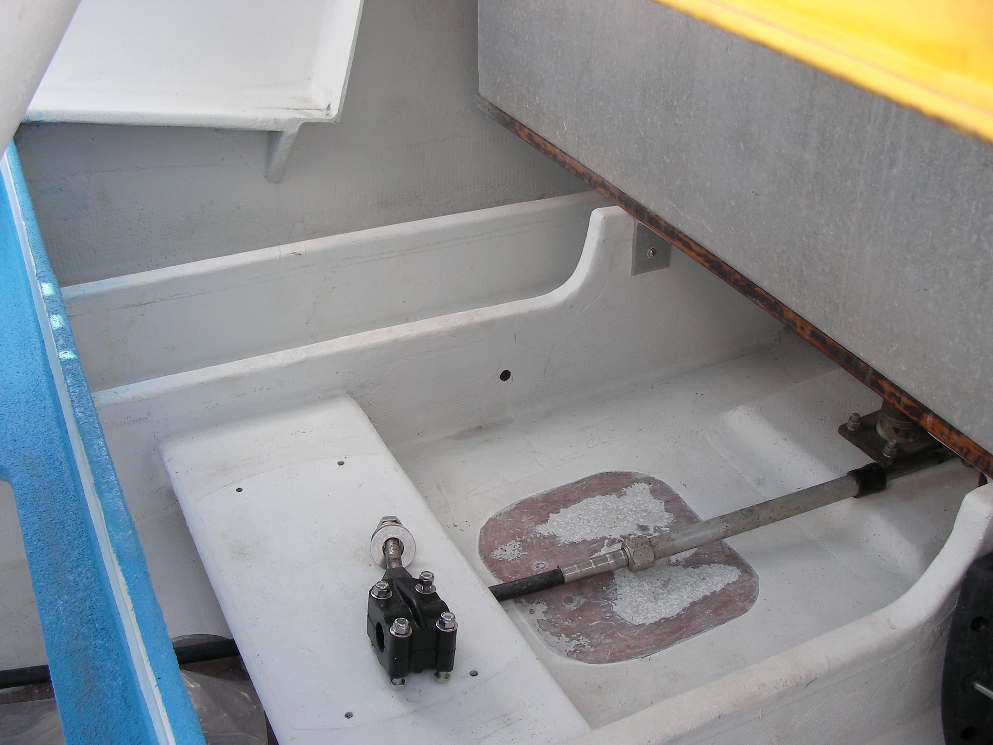
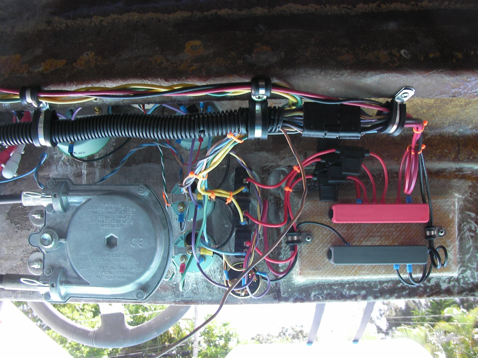
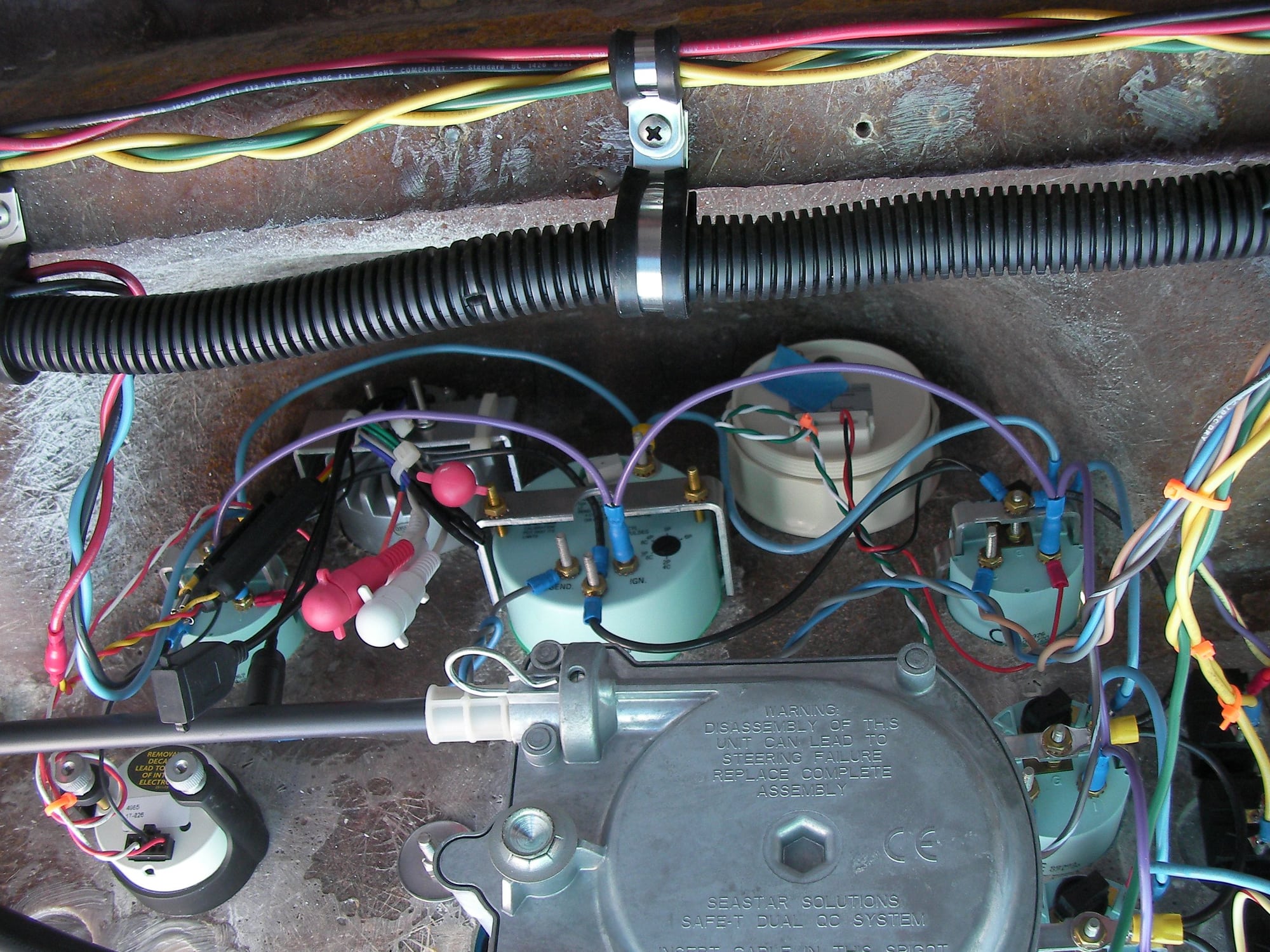
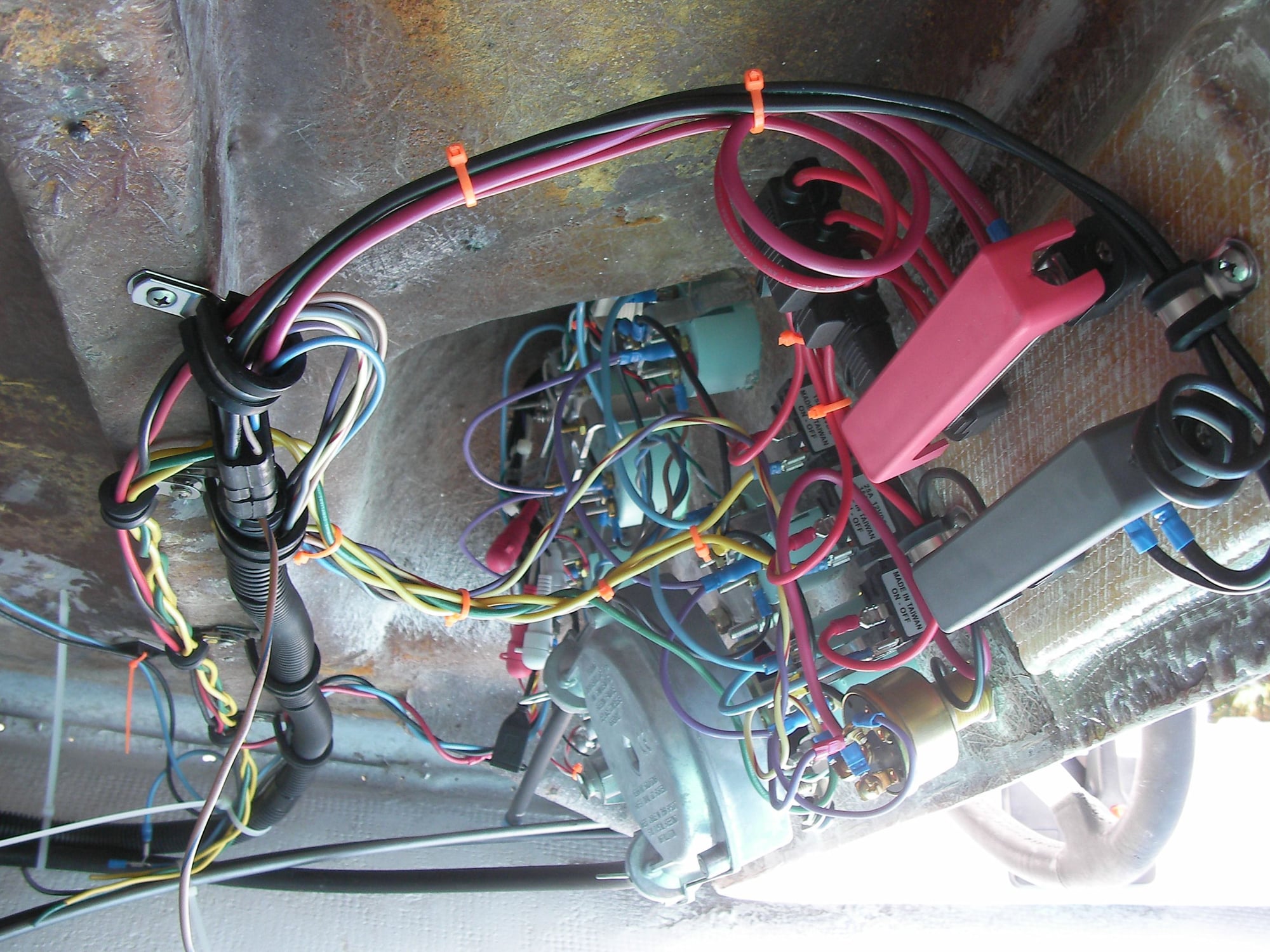
I am thoroughly confused,,,, but first, found out the shaft is bent, this is actually good news because the new shafts are dual tapered and go in/out in a few minutes vs. the old style 2 hour removal/ 500 degree oven for reinstall of the coupler on the shaft.
this will go along way when it comes to bedding and glassing the stern tube in.
meanwhile i started dressing the engine then move on to wiring, but a riser bolt broke in the manifold before it reached 10 ft pnds.
that was a week ago.
today i just jumped on wiring worry about the riser bolt when she's ready to start.
i have every new wire accounted for except
the volt meter
the alternator
the circuit breaker
and theres a brown with blue tracer on the engine and boat harness but not the dash harness.
there is one 10g red wire leaving the alt/dash side of the circuit breaker that cannot be explained.
i'm making drawings and flow charts and still cannot see this volt alt brkr mess.
i'm right back at grind off the hin and leave it somewhere
08-01-2021 | 06:45 AM
#127
Thread Starter
Registered
Joined: May 2009
Posts: 1,941
Likes: 526
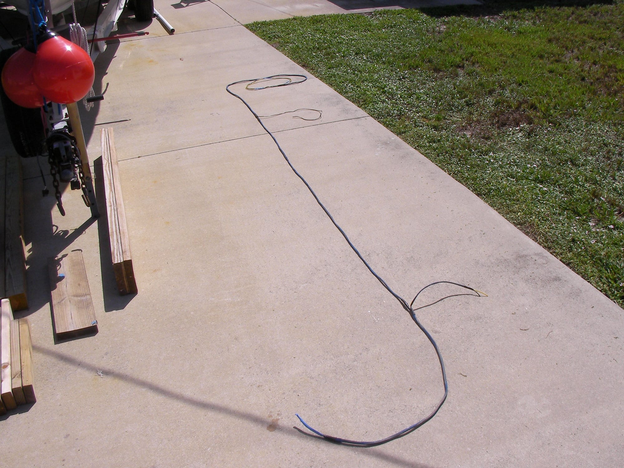
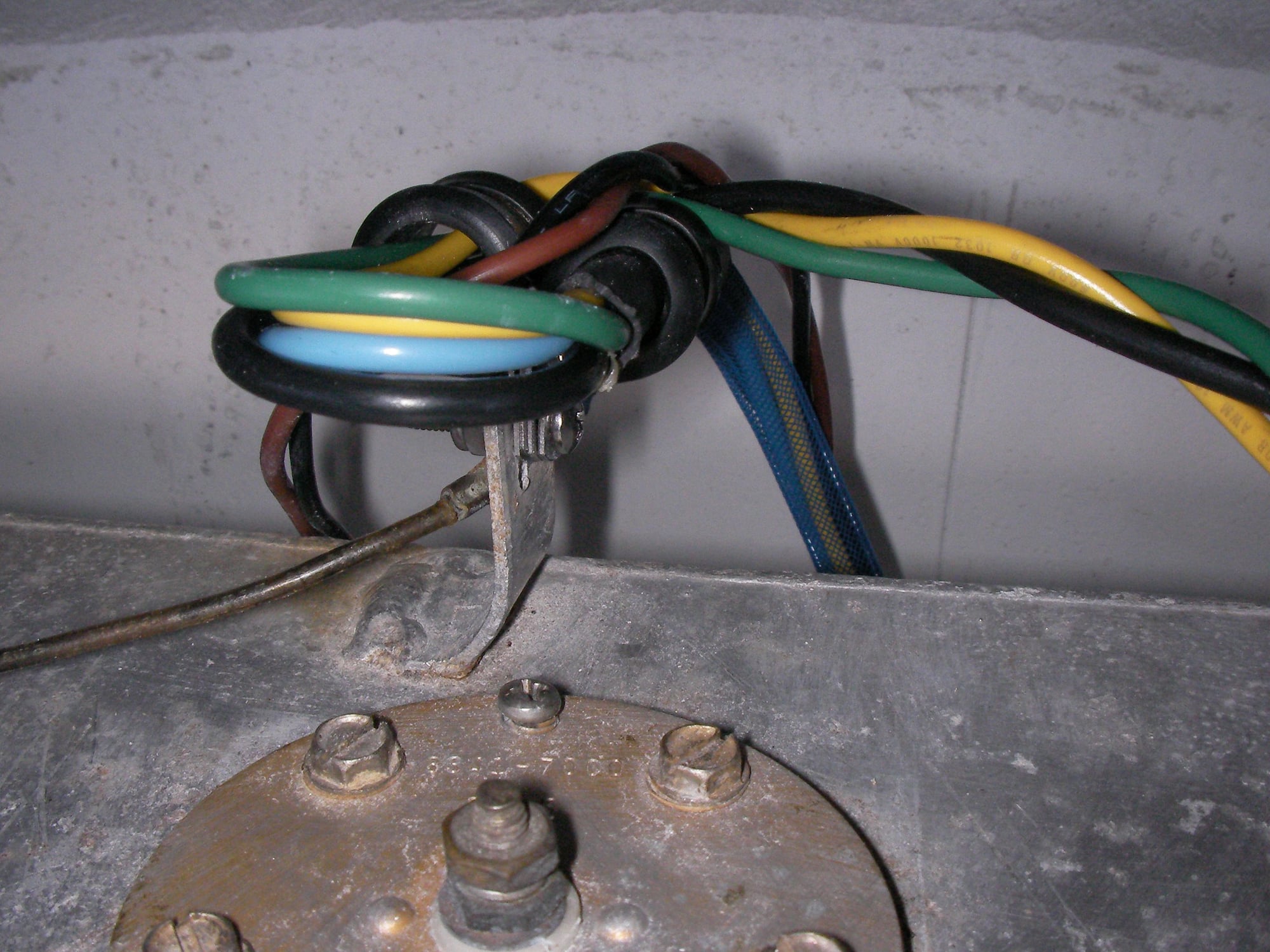
Accy and fuel level boat side harness, i didn't have enough pink and another color, so it's not abc. Loomed it in sections around the bilge pump and rear ground The dash side accy is twisted 2 over 1
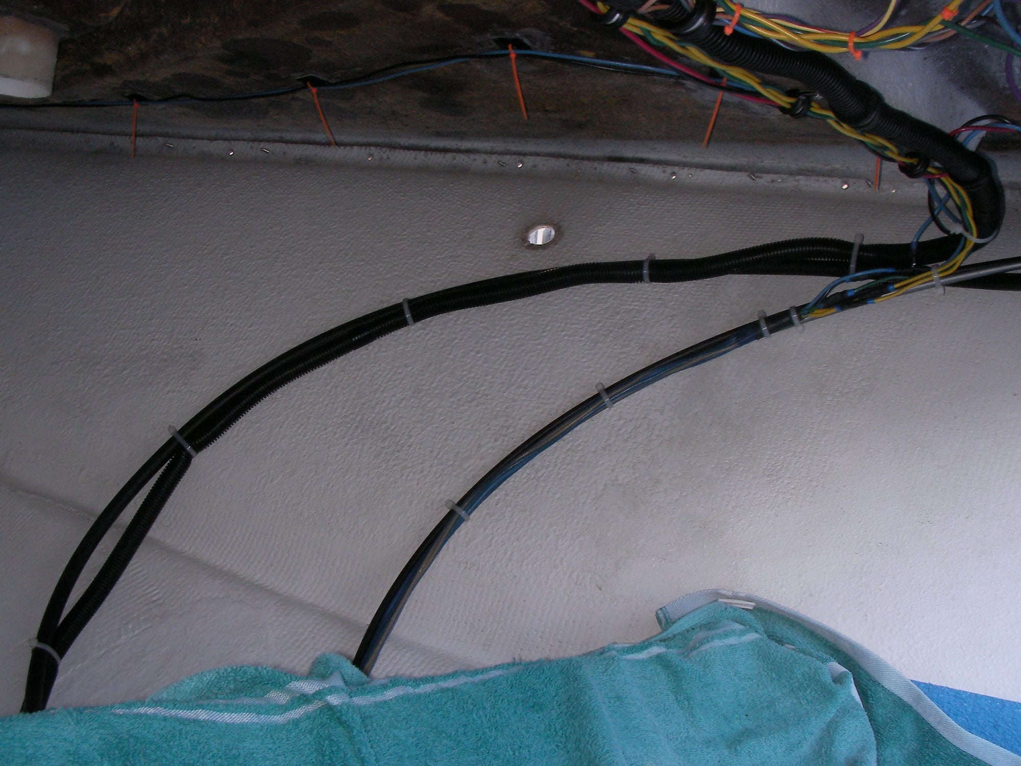
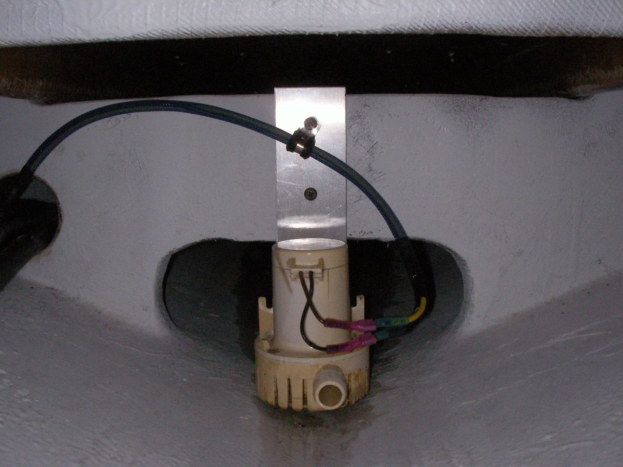
In theory, the only connection that could get wet is the bilge pump.

Same game, get it in then 1 at a time pull off, apply 4200 and reinstall the clamps.
The harness ended perfectly (by pure luck) with plenty of the wrong colored wires to hook up the back end.
08-02-2021 | 12:28 PM
#128
Thread Starter
Registered
Joined: May 2009
Posts: 1,941
Likes: 526
All day yesterday cutting out old silicone from the dash back then toothbrushing it all clean, then fresh silicone around the joint and the old screw holes.
From the dash forward the hull/deck arent bonded and it needed the rivets drilled out and screwed back together tight, did that a while ago.
It went back on in the original holes by hand with 1 size larger screws with nice big flat heads that i got from overtons.
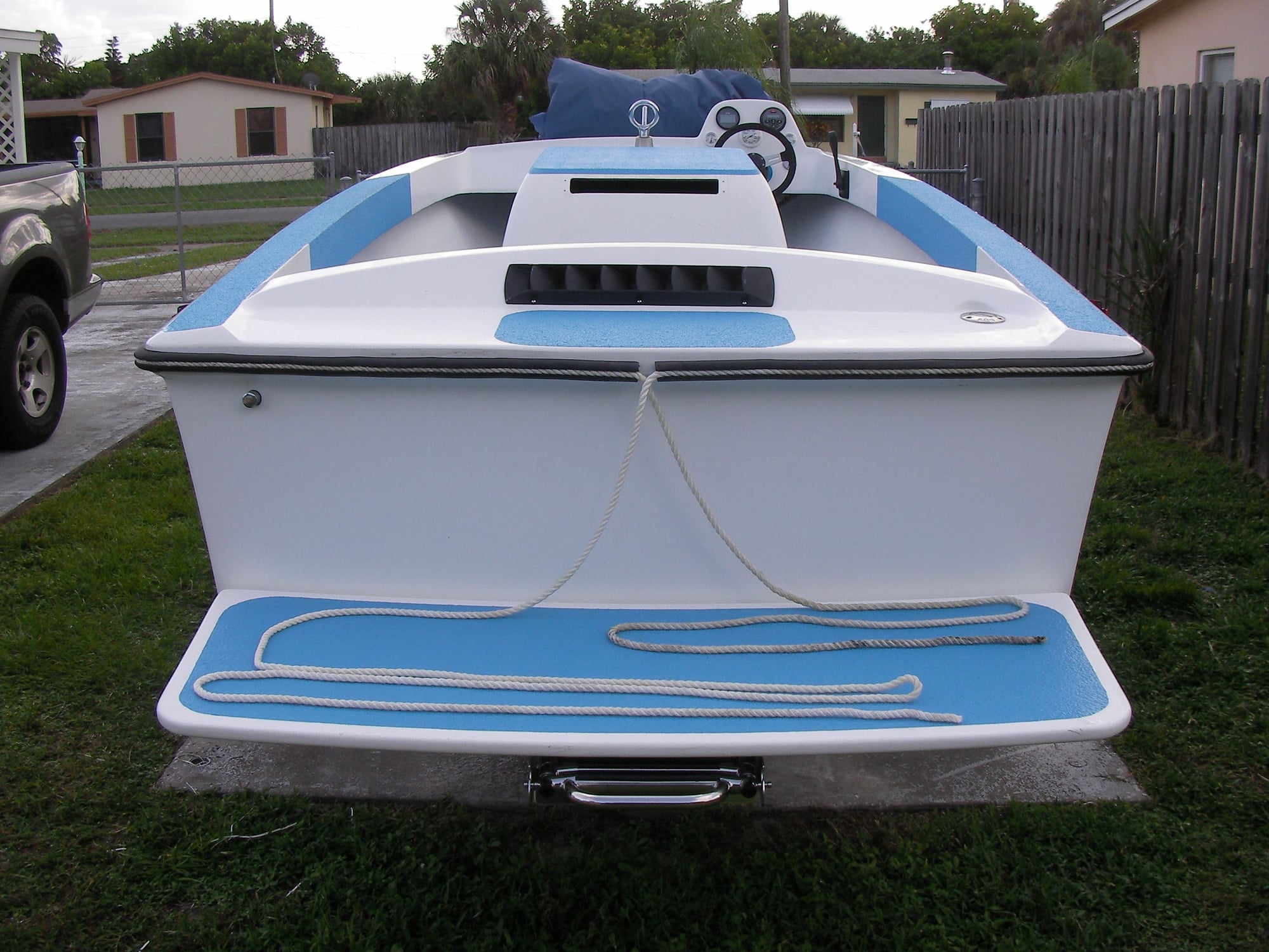
The rail calls for 5/8 rope, i had new 3/8 anchor line hanging in the living room closet.
Last edited by outonsafari; 08-02-2021 at 12:31 PM.


