

Water pickup for intercooler

 03-08-2025 | 06:33 PM
#13
Registered

Joined: Jan 2006
Posts: 3,601
Likes: 1,169
From: taxachusetts
I'd put the pick up no more than 6" from the bottom of the v on the port side.keep the pick up tube's diameter about 1/2 of it below the boat.then cut a v groove into the bottom of the boat.that should keep the water disturbance to the prop to a minimum.
03-09-2025 | 11:49 AM
#14
Driver-441
Joined: Aug 2004
Posts: 12,017
Likes: 1,527
From: Lake George
Whenever possible we avoid running a second stage for the intercooler. Causes more problems than it solves. A Teague adjustable water pickup will be your best friend.
Sometimes, we even run an external for the engine and use the drive for the intercooler.
In cases where its unavoidable, we do run 2 or even 3 stage pumps, but your Baja will do just fine. Start with it 3/4 below the bottom.
Sometimes, we even run an external for the engine and use the drive for the intercooler.
In cases where its unavoidable, we do run 2 or even 3 stage pumps, but your Baja will do just fine. Start with it 3/4 below the bottom.
03-11-2025 | 05:01 PM
#15
Registered
Joined: Oct 2022
Posts: 290
Likes: 92
From: WI
Whenever possible we avoid running a second stage for the intercooler. Causes more problems than it solves. A Teague adjustable water pickup will be your best friend.
Sometimes, we even run an external for the engine and use the drive for the intercooler.
In cases where its unavoidable, we do run 2 or even 3 stage pumps, but your Baja will do just fine. Start with it 3/4 below the bottom.
Sometimes, we even run an external for the engine and use the drive for the intercooler.
In cases where its unavoidable, we do run 2 or even 3 stage pumps, but your Baja will do just fine. Start with it 3/4 below the bottom.
03-12-2025 | 05:43 AM
#16
VIP Member

Joined: Jul 2017
Posts: 1,740
Likes: 298
From: Sodus MI
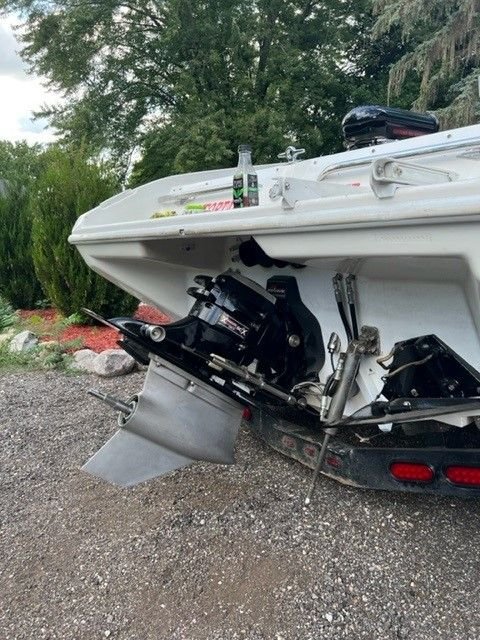
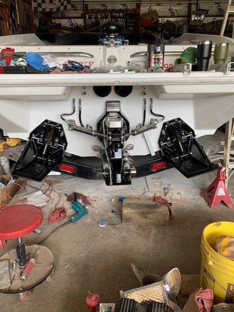
Wish I had better pics of it handy but mine is the square tube next to the trim tab under the steering ram. I wasn't a fan of any of the store bought ones so I made this one out of 1 1/2" square stainless. I tapered the bottom so the transom side was above flush and tapered the other end down to sort of a scoop shape if that makes sense. It is roughly 1/2-3/4 below flush on the outside edge and I did a plate on top to connect to the transom and I did a pipe through and a -16 an fitting welded on the inside. I run it direct to the IC. I originally had one -12 an dump and on the first drive I realized I screwed up as at 25 mph my pressure skyrocketed. I now have two -12 an dumps off the IC and at WOT the pressure sits right at 15-18 psi with no pressure relief valve. I was concerned of the relief sticking at some point and didn't want one more thing to worry about so I sized the dumps to not have to worry about it. As far as how far off centerline...I would have to put a tape on it but I figured out inside of the boat where I needed it to come through and then angled it outward until the square was the same as the rise of the transom. I believe the top is probably 24-30ish off center and the bottom is a few inches more than that. Hope all of this makes sense...little tough to put into words without better pics lol...I'll see if I have a better one straight on from the back


 03-12-2025 | 07:39 AM
#19
VIP Member

Joined: Jun 2021
Posts: 3,549
Likes: 2,146
From: SW Ohio
Wish I had better pics of it handy but mine is the square tube next to the trim tab under the steering ram. I wasn't a fan of any of the store bought ones so I made this one out of 1 1/2" square stainless. I tapered the bottom so the transom side was above flush and tapered the other end down to sort of a scoop shape if that makes sense. It is roughly 1/2-3/4 below flush on the outside edge and I did a plate on top to connect to the transom and I did a pipe through and a -16 an fitting welded on the inside. I run it direct to the IC. I originally had one -12 an dump and on the first drive I realized I screwed up as at 25 mph my pressure skyrocketed. I now have two -12 an dumps off the IC and at WOT the pressure sits right at 15-18 psi with no pressure relief valve. I was concerned of the relief sticking at some point and didn't want one more thing to worry about so I sized the dumps to not have to worry about it. As far as how far off centerline...I would have to put a tape on it but I figured out inside of the boat where I needed it to come through and then angled it outward until the square was the same as the rise of the transom. I believe the top is probably 24-30ish off center and the bottom is a few inches more than that. Hope all of this makes sense...little tough to put into words without better pics lol...I'll see if I have a better one straight on from the back
Could you have just restricted the flow at the pickup? We use a similar approach in our model boats, with the cooling water pickup in the rudder blade. For my 3.5cc boat, for example, there is a �.040" hole in the face of the rudder blade, and I use a ziptie on the hose connected to the outlet nipple on top of the rudder blade, restricting flow. I am amazed at how much water that �.040" hole puts through the system. Some have even gone to the point of putting a needle valve in line, so they can adjust it with a flow meter to account for ambient water temps. This is done to keep from over cooling the engine, but it would work the same for this application as well, in controlling pressure. Obviously, more than a zip tie would be required, but I could see an orifice "pill" used to accomplish the same thing. Or, as Saris mentioned, adjusting the depth of the pickup? As an alternative to multiple dumps? Just wondering....
Thanks. Brad.
 03-12-2025 | 08:53 AM
#20
Driver-441
Joined: Aug 2004
Posts: 12,017
Likes: 1,527
From: Lake George
Not a fan of bottom mounted especially on a balsa cored boat. Skater used to do them and now doesnt as well. Too many delam issues.

