

We hurt the 496....
 04-22-2025 | 04:25 AM
#511
Registered

Joined: Jun 2020
Posts: 518
Likes: 187
From: Holland MI
Ryan,
I didn’t install the transom ass’y bits, so I don’t know for certain. I’m taking him for his word they are all in there correctly. I will say, though, that we’ve been both low and high, as far as misalignment, so I d say it’s all good on that front.
How do you ensure the bearing is seated square?
Thanks. Brad.
You will never get it aligned without those double wound washers
 04-22-2025 | 04:41 AM
#512
Thread Starter
VIP Member

Joined: Jun 2021
Posts: 3,477
Likes: 2,100
From: SW Ohio
If you have been all the way high, and all the way low with the front mounts, and the bar still doesn't slide in, I would tend to think the back felt washers and spring are missing. The gimbal race is seated square in the transom assembly. The bearing is free to pivot it where you want. With the bearing appearing "square" the alignment bar level with the boat, and perpendicular with the transom, can you get your finger back there to feel where the alignment bar is in relation to the coupler?
You will never get it aligned without those double wound washers
You will never get it aligned without those double wound washers
Good to see I’m not the only one up at these stupid hours…..
The felt washers are definitely there, and I’m pretty sure the “springs” are, too.
By “high and low” I mean I’ve seen the bar kick both up and down when the taper at the end of the alignment tool contacts the coupler. That leads me to believe all the bits are there.
”Put your finger in there”…. You mean from the inside, correct? Between the engine and transom ass’y? I’ll have to check. It’s pretty snug back there and the stack up is correct.
For reference, my setup has the “extended” snout coupler. Not sure if this makes a difference.
Thanks. Brad.
Last edited by Brad Christy; 04-22-2025 at 08:23 AM.
 04-22-2025 | 08:44 AM
#513
Registered
Joined: Jun 2020
Posts: 518
Likes: 187
From: Holland MI
Ryan,
Good to see I’m not the only one up at these stupid hours…..
The felt washers are definitely there, and I’m pretty sure the “springs” are, too.
By “high and low” I mean I’ve seen the bar kick both up and down when the taper at the end of the alignment tool contacts the coupler. That leads me to believe all the bits are there.
”Put your finger in there”…. You mean from the inside, correct? Between the engine and transom ass’y? I’ll have to check. It’s pretty snug back there and the stack up is correct.
For reference, my setup has the “extended” snout coupler. Not sure if this makes a difference.
Thanks. Brad.
Yes, I like to try and get the alignment bar as square as my eye can visually see, push straight in, then try and feel where the alignment bar and coupler meet inside the bilge to figure out if I'm high, low, or side to side. After i have the bar at least sliding in and out, i use grease marks on the alignment bar to adjust the rest of the way
04-22-2025 | 09:00 AM
#514
Thread Starter
VIP Member
Joined: Jun 2021
Posts: 3,477
Likes: 2,100
From: SW Ohio
Have you guys tried adjusting the front motor mount nuts?
Yes, I like to try and get the alignment bar as square as my eye can visually see, push straight in, then try and feel where the alignment bar and coupler meet inside the bilge to figure out if I'm high, low, or side to side. After i have the bar at least sliding in and out, i use grease marks on the alignment bar to adjust the rest of the way
Yes, I like to try and get the alignment bar as square as my eye can visually see, push straight in, then try and feel where the alignment bar and coupler meet inside the bilge to figure out if I'm high, low, or side to side. After i have the bar at least sliding in and out, i use grease marks on the alignment bar to adjust the rest of the way
The front adjustment nuts are what we've been "up and down" all over the place with. There really isn't any adjustment to the rear mounting points, is there?
As of right now, we don't have any entry of the alignment tool into the coupler at all. We can tell which way it's off by, by which way the tool kicks off when it comes into contact with the coupler, but it won't even begin to go into the spline.
Thanks. Brad.
04-22-2025 | 10:11 AM
#515
Registered
Joined: Oct 2024
Posts: 96
Likes: 39
From: York Haven, PA
Brad,
If you are starting from scratch, the procedure should be as follows:
1: Slightly loosen the rear mounts
2. Install a 1" bar in the coupler
3. Lift the weight off the engine with a hoist and leveler to hold the engine roughly level and move the engine up and down until the 1" bar is roughly in the center of the gimbal bearing.
4. Adjust the front mount nuts so the lower nuts are just touching the engine mounts, that will ensure they are level with the rear mounts and not trying to twist the engine.
5. Re-torque the rear mounts
6. Remove the engine hoist
7. Install alignment tool and push on it while whacking the back end left, right, up, and down until the alignment bar goes into the coupler
8. Look at the witness marks on the alignment tool and make fine adjustments to the lower mount nuts in equal turns on both sides
Last edited by ashipshow; 04-22-2025 at 10:13 AM.
04-22-2025 | 01:04 PM
#516
Thread Starter
VIP Member
Joined: Jun 2021
Posts: 3,477
Likes: 2,100
From: SW Ohio
Guys,

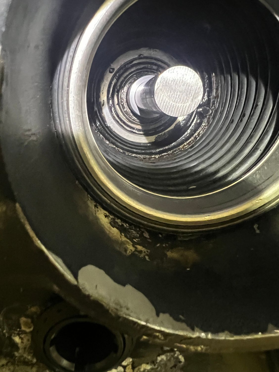
So this is what I’ve got. The sleeve has MAYBE .0015” clearance over the ř1” shaft, and the OD is MAYBE .0005” smaller in diameter than the equivalent diameter of the alignment tool, and the shaft is actually bigger by ~.005” than the equivalent diameter of the alignment tool. All in all, it’s a REALLY good representation of the alignment tool that allows me to slip it into the spline first, then slip into the bearing. Fits like a glove. I wouldn’t say it’s perfect, but it’s close. Even if I slip the sleeve into the bearing first, the shaft slips in easily. But the alignment tool….? Ain’t happinin’…. I’ve checked the alignment tool, and it doesn’t appear to have any significant run-out, but I’ve only done a rough check until my bigger lathe is available (sometime this afternoon),
Thoughts….?
Thanks. Brad.
Last edited by Brad Christy; 04-22-2025 at 01:47 PM.
04-22-2025 | 02:14 PM
#518
Registered
Joined: Jun 2020
Posts: 518
Likes: 187
From: Holland MI
Maybe i misssed it, but is that a new gimbal bearing? If not i would be replacing it while you have it apart.
04-22-2025 | 02:42 PM
#519
Registered
Joined: Oct 2024
Posts: 96
Likes: 39
From: York Haven, PA
Up on the adjustment nuts goes down on the coupler.. The rear mounts are kind of like the pivot point and the coupler is aft of the pivot, so its opposite.
04-22-2025 | 03:10 PM
#520
Thread Starter
VIP Member
Joined: Jun 2021
Posts: 3,477
Likes: 2,100
From: SW Ohio
That’s kinda what my thoughts were, thinking like an engineer, but I got what appeared to be the opposite result. I’m tinkering with it now.
So, how would you suggest lifting the front of the engine? The intercooler is mounted on the front lift ring, which is way off to the side, anyhow. Can I loop around the crank pulley with a nylon strap?
Thanks. Brad.
Last edited by Brad Christy; 04-22-2025 at 03:12 PM.

