

We hurt the 496....
 04-23-2025 | 02:00 PM
#531
Thread Starter
VIP Member

Joined: Jun 2021
Posts: 3,533
Likes: 2,142
From: SW Ohio
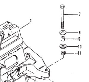
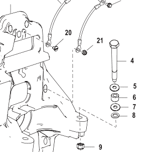
While you have the engine back out, make sure you have the right set of parts in place for the rear mounts.. I'm not sure what your drive serial number is, but somewhere around the time of your stuff, mercruiser switched from using the double wound lock washer to not using it, which would mess up the height of the rear mounts. I'd triple check everything serial number wise and make sure you have the right combination of stuff.
Also, yes, change the gimbal bearing lol.. With all your stuff already off, its like a 10 minute job.. as long as you have or rent a slide hammer from the auto parts store (its free)..
While I'm at it, I'll give a shameless plug for my own video lol..
Changing Gimbal Bearing
While I'm at it, I'll give a shameless plug for my own video lol..
Changing Gimbal Bearing
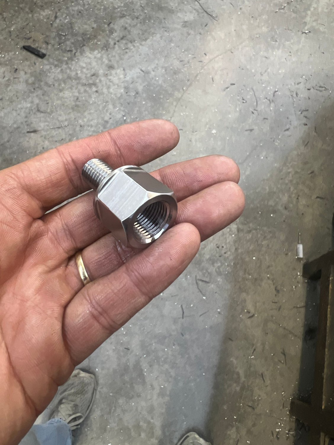
Fortunately, we are not pulling the engine. I was able to lift and tilt the engine enough to gain access to the lower end of the dipstick tube and remove the broken part. Fortunately, the broken section that was in the oil pan came out pretty easily with some picking with my thumbnail.
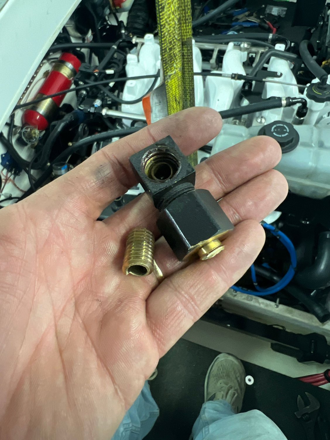
I am in the process of making a replacement out of 316ss, and it should be back together by this time tomorrow.
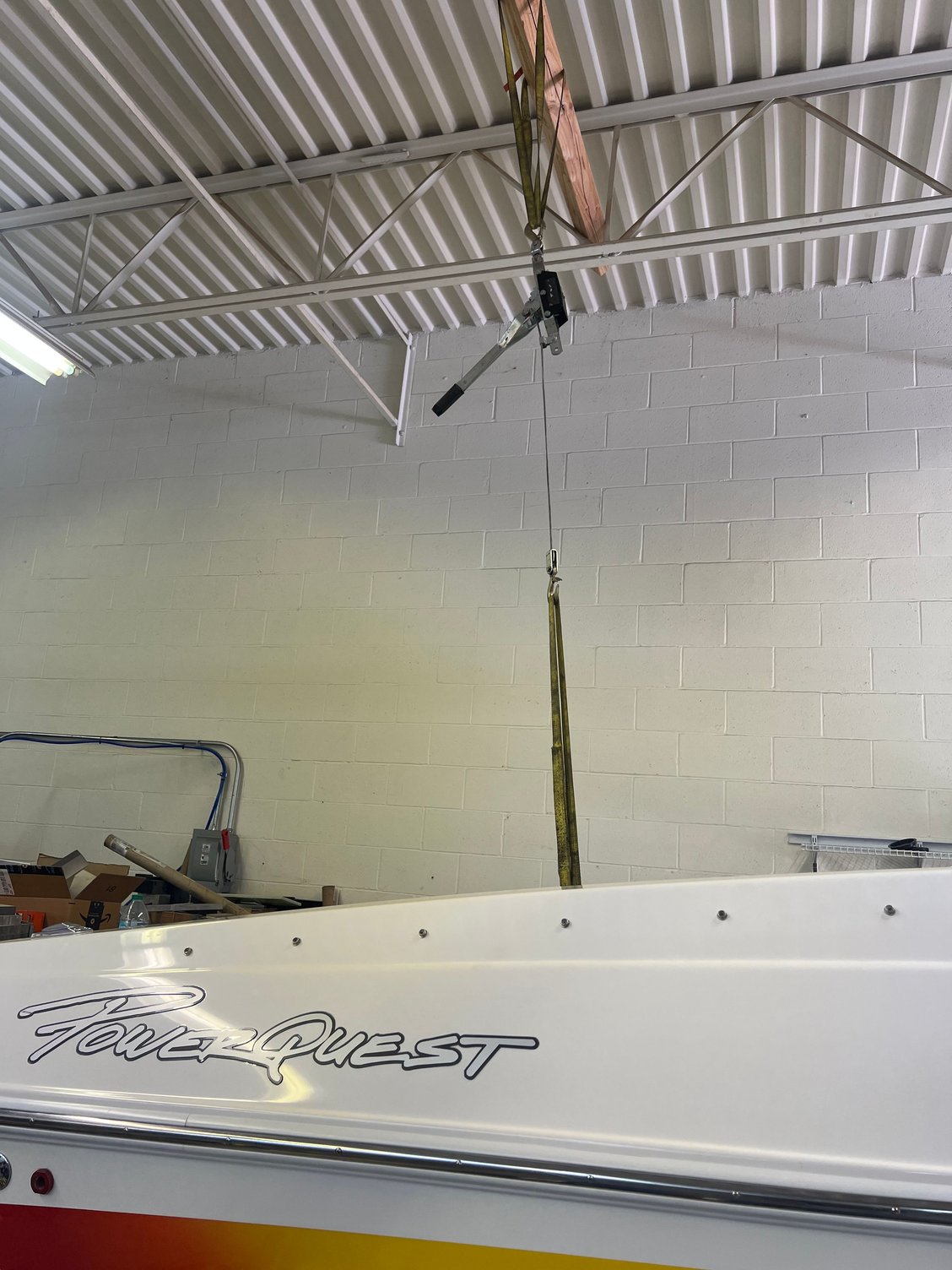
Ironically, I think I was actually starting to get somewhere on the alignment thing. I used a come-a-long hung from the rafters of my building to lift the rear of the engine. I was hoping to gain access to the bits you refer to, but the extended snout of the coupler hit a rib on the transom plate, and limited the lift. I tried feeling between the bell housing mounting points and the transom plate, but couldn�t really tell anything. So I lowered it back into place. By whatever means, I think it settled in a bit lower, and I was starting to make some headway when the broken dipstick tube was discovered. As soon as I get that all back together, I�ll start back on that effort. News at eleven�.
Yes. We will be installing a new gimbal bearing. Should be in hand tomorrow.
Thanks. Brad.
Last edited by Brad Christy; 04-23-2025 at 02:02 PM.

 04-24-2025 | 10:20 PM
#533
Registered

Joined: Aug 2019
Posts: 1,250
Likes: 420
From: BC
Nice machining Brad.
Some advice...don't even hint to the CFO how much time you're spending on this...
Lining things up, and having zero joy, and ads to the issues that promote stress and deny critical thinking.
Some good info on this post on how to prep for an engine/drive install.
Also a good practice once you get engine and drive in, is to check crank endplay, ensuring the crank didn't get pinched/or pushed.
04-30-2025 | 07:02 PM
#534
Thread Starter
VIP Member
Joined: Jun 2021
Posts: 3,533
Likes: 2,142
From: SW Ohio
Guys,
On to the next conundrum�.
In the process of this, in an effort to preserve the 555 harness, I bought a new 10-pin cannon harness, which the builder grafted back to the engine. I�m now working on finalizing the remaining wiring; specifically the trim stuff. I�ve got three wires coming from the cannon harness, and found three matching wires coming from �the boat�, going into the cannon plug:

And I found these wires/connecters coming from the 555 harness, labeled "transom harness":
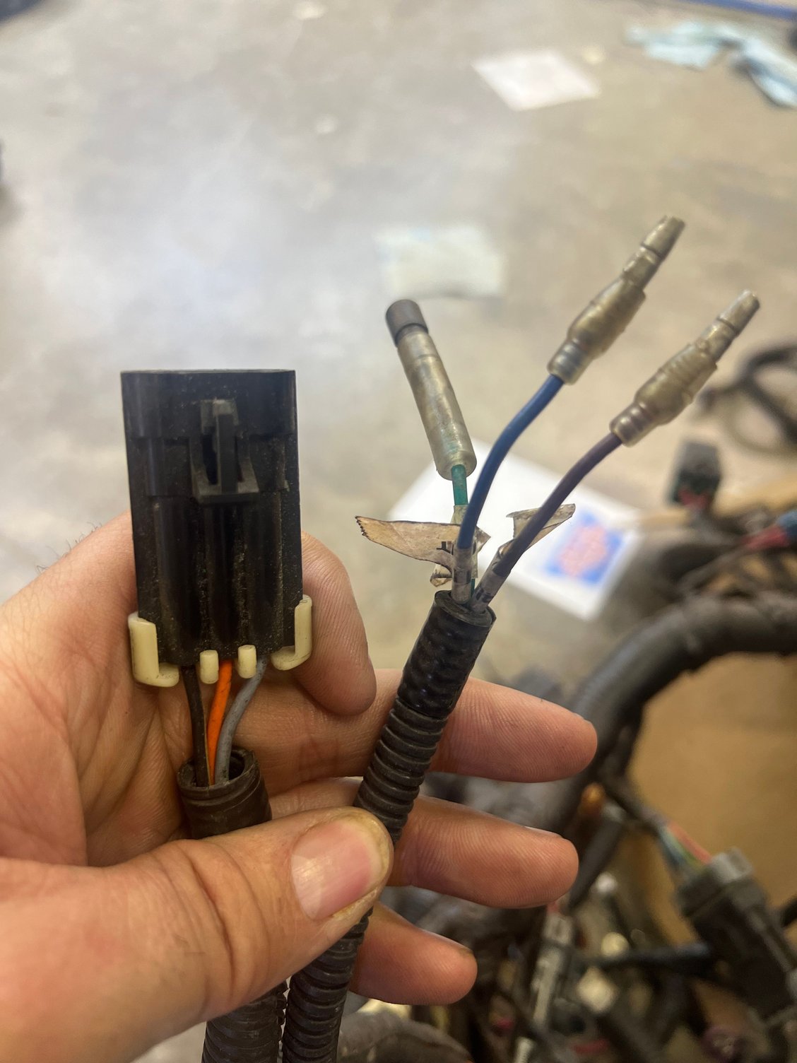
I have matching connecters at the transom plate. The two bullet connectors are the limit switch, per labeling of the two matching wires on the harness, (which I�m assuming are interchangeable, seeing it�s just a switch) and the three-wire connecter should be the trim sender, but which wire is which�? The colors are different from the cannon harness (grey, tan and brown/white) and the transom plate connecter (all black, one not labeled, the other two labeled "B" and C"). I�ve tried looking up the cannon plug wiring, but I haven�t found a 496 specific diagram, and it would appear that Merc substituted some of the cannon plug wires that are not used for the 496 for these trim connections.
Any Help?
Thanks. Brad.
On to the next conundrum�.
In the process of this, in an effort to preserve the 555 harness, I bought a new 10-pin cannon harness, which the builder grafted back to the engine. I�m now working on finalizing the remaining wiring; specifically the trim stuff. I�ve got three wires coming from the cannon harness, and found three matching wires coming from �the boat�, going into the cannon plug:
And I found these wires/connecters coming from the 555 harness, labeled "transom harness":
I have matching connecters at the transom plate. The two bullet connectors are the limit switch, per labeling of the two matching wires on the harness, (which I�m assuming are interchangeable, seeing it�s just a switch) and the three-wire connecter should be the trim sender, but which wire is which�? The colors are different from the cannon harness (grey, tan and brown/white) and the transom plate connecter (all black, one not labeled, the other two labeled "B" and C"). I�ve tried looking up the cannon plug wiring, but I haven�t found a 496 specific diagram, and it would appear that Merc substituted some of the cannon plug wires that are not used for the 496 for these trim connections.
Any Help?
Thanks. Brad.
Last edited by Brad Christy; 05-01-2025 at 07:25 AM.
05-01-2025 | 08:57 AM
#535
Registered
Joined: Oct 2024
Posts: 96
Likes: 39
From: York Haven, PA
Do you have a 3 wire trim sender? or 2 wire? If you have a smartcraft system with 3 wire, you will use that 3 wire plug as that is for the "digital trim" sender...
As for the wiring, I don't remember which is power and which is ground, but I do remember that the orange wire is the sensor feedback to the smartcraft system.
Unless you can find the wiring diagram somewhere, you might need to give the engine power and measure the voltage on the gray and black wires to see what the polarity is.
 05-01-2025 | 09:10 AM
#537
Thread Starter
VIP Member
Joined: Jun 2021
Posts: 3,533
Likes: 2,142
From: SW Ohio
Do you have a 3 wire trim sender? or 2 wire? If you have a smartcraft system with 3 wire, you will use that 3 wire plug as that is for the "digital trim" sender...
As for the wiring, I don't remember which is power and which is ground, but I do remember that the orange wire is the sensor feedback to the smartcraft system.
Unless you can find the wiring diagram somewhere, you might need to give the engine power and measure the voltage on the gray and black wires to see what the polarity is.
As for the wiring, I don't remember which is power and which is ground, but I do remember that the orange wire is the sensor feedback to the smartcraft system.
Unless you can find the wiring diagram somewhere, you might need to give the engine power and measure the voltage on the gray and black wires to see what the polarity is.
It is a 3-wire connecter, and the transom ass'y is SmartCraft, but I don't think it was actually in use.
I'm gathering that the three wires that are exiting the cannon plug have nothing to do with the trim sender or limit. Interwebs seems pretty adamant the grey is tach signal and tan in engine temp signal to audible dash alarm.
I just need to be connect the trim sender to the gage at the dash and connect the limit switch. I'm assuming that "B" in your diagram is the limit switch and "E" is the sender connecter...? Does all this have to go through the SmartCraft committee wiring?
Thanks. Brad.
05-01-2025 | 09:15 AM
#538
Registered
Joined: Oct 2024
Posts: 96
Likes: 39
From: York Haven, PA
My 496 setup is a 2006 and doesn't use the trim limit.. I guess that is handled through the smartcraft?? It only uses the 3 wire digital trim connector (E) and the two analog trim sender wires for the gauge (bullet connectors on my harness, orange with white stripe and black).
05-01-2025 | 09:24 AM
#539
Thread Starter
VIP Member
Joined: Jun 2021
Posts: 3,533
Likes: 2,142
From: SW Ohio
My 496 setup is a 2006 and doesn't use the trim limit.. I guess that is handled through the smartcraft?? It only uses the 3 wire digital trim connector (E) and the two analog trim sender wires for the gauge (bullet connectors on my harness, orange with white stripe and black).

That�s what I have. The connecter to the right is capped (bridged?), and is labeled �steering/speedo pitpot�
But I�m not using any of that anymore. The entire 555 harness has been replaced with the Holley HP harness, which obviously has NONE of this.
I�m just hoping someone can tell me how to connect the sender to the gage. I could even go without the limit switch, if I have to, if I have a gauge.
Thanks. Brad.
05-01-2025 | 09:31 AM
#540
Registered
Joined: Oct 2024
Posts: 96
Likes: 39
From: York Haven, PA
AShipShow,
It is a 3-wire connecter, and the transom ass'y is SmartCraft, but I don't think it was actually in use.
I'm gathering that the three wires that are exiting the cannon plug have nothing to do with the trim sender or limit. Interwebs seems pretty adamant the grey is tach signal and tan in engine temp signal to audible dash alarm.
I just need to be connect the trim sender to the gage at the dash and connect the limit switch. I'm assuming that "B" in your diagram is the limit switch and "E" is the sender connecter...? Does all this have to go through the SmartCraft committee wiring?
Thanks. Brad.
If your not using the 3 wire digital trim sender, then you will need to make sure you have the 2 wire analog sender for the gauge and 2 wire limit switch - this should be the kit part number

